
Page 56 - Schaum's Outline of Theory and Problems of Electric Circuits
P. 56
ANALYSIS METHODS
CHAP. 4]
ð27Þð4 þ 23Þ 45
R eq ¼ 47 þ ¼ 60:5
54
200
I T ¼ ¼ 3:31 A
60:5
0 27
I 23
¼ ð3:31Þ¼ 1:65 A
54
When the 20-A source acts alone, the 200-V source is replaced by a short circuit, Fig. 4-11(c). The equivalent
resistance to the left of the source is
ð27Þð47Þ
R eq ¼ 4 þ ¼ 21:15
74
21:15
00
Then I 23
¼ ð20Þ¼ 9:58 A
21:15 þ 23
The total current in the 23-
resistor is
00
0
I 23
¼ I 23
þ I 23
¼ 11:23 A
´
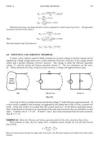
4.9 THEVENIN’S AND NORTON’S THEOREMS
A linear, active, resistive network which contains one or more voltage or current sources can be
replaced by a single voltage source and a series resistance (The ´venin’s theorem), or by a single current
source and a parallel resistance (Norton’s theorem). The voltage is called the The ´venin equivalent
0
0
voltage, V , and the current the Norton equivalent current, I . The two resistances are the same,
0
R . When terminals ab in Fig. 4-12(a) are open-circuited, a voltage will appear between them.
Fig. 4-12
0
From Fig. 4-12(b) it is evident that this must be the voltage V of the The ´ venin equivalent circuit. If
a short circuit is applied to the terminals, as suggested by the dashed line in Fig. 4-12(a), a current will
0
result. From Fig. 4-12(c) it is evident that this current must be I of the Norton equivalent circuit.
Now, if the circuits in (b) and (c) are equivalents of the same active network, they are equivalent to each
0
0
0
0
other. It follows that I ¼ V =R . 0 If both V and I have been determined from the active network,
0
0
0
then R ¼ V =I .
EXAMPLE 4.8 Obtain the The ´ venin and Norton equivalent circuits for the active network in Fig. 4-13(a).
With terminals ab open, the two sources drive a clockwise current through the 3-
and 6-
resistors
[Fig. 4-13(b)].
20 þ 10 30
I ¼ ¼ A
3 þ 6 9
Since no current passes through the upper right 3-
resistor, the The ´ venin voltage can be taken from either active
branch: