
Page 53 - Schaum's Outline of Theory and Problems of Electric Circuits
P. 53
42
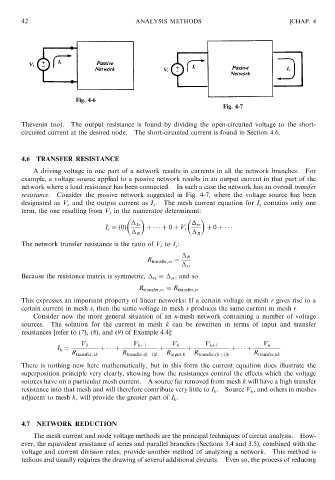
Fig. 4-6 ANALYSIS METHODS [CHAP. 4
Fig. 4-7
The ´ venin too). The output resistance is found by dividing the open-circuited voltage to the short-
circuited current at the desired node. The short-circuited current is found in Section 4.6.
4.6 TRANSFER RESISTANCE
A driving voltage in one part of a network results in currents in all the network branches. For
example, a voltage source applied to a passive network results in an output current in that part of the
network where a load resistance has been connected. In such a case the network has an overall transfer
resistance. Consider the passive network suggested in Fig. 4-7, where the voltage source has been
designated as V r and the output current as I s . The mesh current equation for I s contains only one
term, the one resulting from V r in the numerator determinant:
1s rs
I s ¼ð0Þ þ þ 0 þ V r þ 0 þ
R R
The network transfer resistance is the ratio of V r to I s :
R
R transfer;rs ¼
rs
Because the resistance matrix is symmetric, ¼ , and so
rs
sr
R transfer;rs ¼ R transfer;sr
This expresses an important property of linear networks: If a certain voltage in mesh r gives rise to a
certain current in mesh s, then the same voltage in mesh s produces the same current in mesh r.
Consider now the more general situation of an n-mesh network containing a number of voltage
sources. The solution for the current in mesh k can be rewritten in terms of input and transfer
resistances [refer to (7), (8), and (9) of Example 4.4]:
V 1 V k 1 V k V kþ1 V n
I k ¼ þ þ þ þ þ þ
R transfer;1k R transfer;ðk 1Þk R input;k R transfer;ðkþ1Þk R transfer;nk
There is nothing new here mathematically, but in this form the current equation does illustrate the
superposition principle very clearly, showing how the resistances control the effects which the voltage
sources have on a particular mesh current. A source far removed from mesh k will have a high transfer
resistance into that mesh and will therefore contribute very little to I k . Source V k , and others in meshes
adjacent to mesh k, will provide the greater part of I k .
4.7 NETWORK REDUCTION
The mesh current and node voltage methods are the principal techniques of circuit analysis. How-
ever, the equivalent resistance of series and parallel branches (Sections 3.4 and 3.5), combined with the
voltage and current division rules, provide another method of analyzing a network. This method is
tedious and usually requires the drawing of several additional circuits. Even so, the process of reducing