
Page 138 - Science at the nanoscale
P. 138
8:11
RPS: PSP0007 - Science-at-Nanoscale
June 9, 2009
Low-Dimensional Nanostructures
128
M, T
1D ballistic conductor
Contact
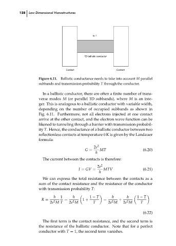
Ballistic conductance needs to take into account M parallel
Figure 6.11.
subbands and transmission probability T through the conductor.
In a ballistic conductor, there are often a finite number of trans-
verse modes M (or parallel 1D subbands), where M is an inte-
ger. This is analogous to a ballistic conductor with variable width,
depending on the number of occupied subbands as shown in
Fig. 6.11. Furthermore, not all electrons injected at one contact
arrive at the other contact, and the electron wave function can be
likened to tunneling through a barrier with transmission probabil-
ity T. Hence, the conductance of a ballistic conductor between two
reflectionless contacts at temperature 0 K is given by the Landauer
formula:
2
2e
G =
h
The current between the contacts is therefore:
2
2e
MTV
(6.21)
I = GV =
h MT Contact (6.20) ch06
We can express the total resistance between the contacts as a
sum of the contact resistance and the resistance of the conductor
with transmission probability T:
h 1 h 1 − T h h 1 − T
R = = 1 + = +
2
2
2
2
2e M T 2e M T 2e M 2e M T
(6.22)
The first term is the contact resistance, and the second term is
the resistance of the ballistic conductor. Note that for a perfect
conductor with T = 1, the second term vanishes.