
Page 124 - Semiconductor Manufacturing Handbook
P. 124
Geng(SMH)_CH09.qxd 04/04/2005 19:42 Page 9.23
MICROLITHOGRAPHY
MICROLITHOGRAPHY 9.23
1
High leakage
current, device fails
0.8 Devices are too slow,
poor bin sort
Frequency 0.6
0.4
Range affects
0.2 timing, which affects
max clock speed
possible
0
150 160 170 180 190 200 210
Gate CD (nm)
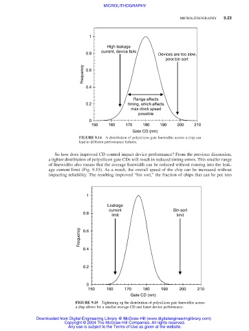
FIGURE 9.14 A distribution of polysilicon gate linewidths across a chip can
lead to different performance failures.
So how does improved CD control impact device performance? From the previous discussion,
a tighter distribution of polysilicon gate CDs will result in reduced timing errors. This smaller range
of linewidths also means that the average linewidth can be reduced without running into the leak-
age current limit (Fig. 9.15). As a result, the overall speed of the chip can be increased without
impacting reliability. The resulting improved “bin sort,” the fraction of chips that can be put into
1
Leakage
current Bin sort
0.8 limit limit
Frequency 0.6
0.4
0.2
0
150 160 170 180 190 200 210
Gate CD (nm)
FIGURE 9.15 Tightening up the distribution of polysilicon gate linewidths across
a chip allows for a smaller average CD and faster device performance.
Downloaded from Digital Engineering Library @ McGraw-Hill (www.digitalengineeringlibrary.com)
Copyright © 2004 The McGraw-Hill Companies. All rights reserved.
Any use is subject to the Terms of Use as given at the website.