Page 153 - Semiconductor Manufacturing Handbook
P. 153

Geng(SMH)_CH12.qxd  04/04/2005  19:49  Page 12.2


                                                      PLASMA ETCHING

                   12.2  WAFER PROCESSING

                                                            positive ions toward the substrate placed on the cathode,
                                                            facilitating sputtering etching. The dc bias can also be influ-
                                                            enced by a separate external power supply.
                                                              Plasma also facilitates etching by means of reactive etchant
                                        Plasma
                                                            species. For example, free fluorine (F) atoms can be generated
                                         Ions,              in SF plasma through dissociation, ionization, and attachment
                                                               6
                                         electrons,         reactions as described next. The F atoms react with silicon
                                         neutrals           atoms spontaneously to form a volatile product SiF that des-
                                                                                                4
                                                            orbs from the substrate surface and is pumped away.
                                  Sheath          Substrate
                                                              Dissociation reactions
                                                                       −
                                               Cathode                e + SF = SF + F + e −
                                                                            6   5
                                                                       −
                                                                      e + SF = SF + F + e −
                                                                            5   4
                                                                       −
                                                                      e + SF = SF + F + e −
                                                                            4   3
                                            (a)
                                                              Ionization reactions
                                                                                 +
                                                                       −
                                                                      e + SF = SF + F + 2e −
                                                                            6
                                                                                5
                               +   V p                                e + SF = SF + F + F + 2e −
                                                                                 +
                                                                       −
                                                                            6   3   2
                                                                       −
                                                                                 +
                                                                      e + SF = SF + F + 2e −
                                                                            4   3
                                                              Attachment reactions
                                                                                 −
                               −   V f                                e + SF = SF + F
                                                                       −
                                                                            6   5
                                                                       −
                                                                                 −
                                                                      e + SF = SF + F
                                           (b)                              4   3
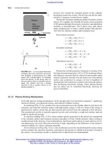
                                                              Plasma has several properties important to etching. First,
                               FIGURE 12.1  (a) Conceptual illustration
                                                                                        5
                                                                                   4
                               of plasma (the lower electrode is powered).  the high electron temperature (10 to 10 K) in plasma allows
                               The discharge is characterized by a bulk  and enhances reactions that are otherwise not possible under
                               region and a sheath region. (b) Potential  normal conditions. Second, ions are drawn out of the plasma
                               across the plasma. At the steady state, the  surface and accelerated to energies of tens to hundreds of
                               electron and ion fluxes to chamber wall are  electronvolts with a direction normal to the electrode surface,
                               equal.  The chamber wall has a floating
                               potential  V that is negative relative to the  thus facilitating anisotropic etching. Third, plasma density
                                      f
                               plasma potential V .         and ion influx can be controlled effectively, allowing for
                                          p
                                                            process flexibility.
                   12.1.2 Plasma Etching Mechanisms
                               Generally, plasma etching mechanisms can be grouped into four functional categories—sputtering,
                               chemical etching, ion-enhanced etching, and sidewall inhibitor etching.
                                 In sputtering (Fig. 12.2a), positive ions are accelerated across the sheath, which is just above the
                               substrate, and strike the substrate surface with high kinetic energy (>100 eV). Some of the energy is
                               transferred to surface atoms that are then ejected and removed from the substrate at low pressure.
                               The resulted etch profile is typically tapered, has low etch selectivity, a rough etch surface, and can
                               result in significant damage.
                                 In chemical etching (Fig. 12.2b), active etchant species generated in the plasma are transported
                               to the substrate surface and chemical reactions take place to form volatile products. Since etching is
                               nondirectional in the absence of ion bombardment, significant undercutting of mask and loss of crit-
                               ical dimensions can result. But etch selectivity is high, depending on the difference in the etchant’s
                               chemical affinity for various substrate materials.
                                 In ion-enhanced etching (Fig. 12.2c), ions accelerated across the sheath disrupt the surface being
                               etched, enhance the chemical reactivity, and improve desorption of volatile etch products formed at
                               the surface. An anisotropic profile is obtained due to directional ion bombardment.
                          Downloaded from Digital Engineering Library @ McGraw-Hill (www.digitalengineeringlibrary.com)
                                     Copyright © 2004 The McGraw-Hill Companies. All rights reserved.
                                       Any use is subject to the Terms of Use as given at the website.
   148   149   150   151   152   153   154   155   156   157   158