
Page 154 - Semiconductor Manufacturing Handbook
P. 154
Geng(SMH)_CH12.qxd 04/04/2005 19:49 Page 12.3
PLASMA ETCHING
PLASMA ETCHING 12.3
Volatile Volatile
Ion Ion
product Neutral product
+ +
(a) Sputtering (c) Ion-enhanced etching
Volatile Ion Volatile
Neutral product Neutral product
+
(b) Chemical etching (d) Sidewall inhibitor
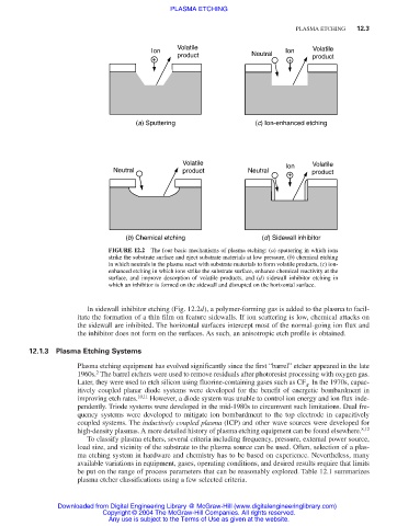
FIGURE 12.2 The four basic mechanisms of plasma etching: (a) sputtering in which ions
strike the substrate surface and eject substrate materials at low pressure, (b) chemical etching
in which neutrals in the plasma react with substrate materials to form volatile products, (c) ion-
enhanced etching in which ions strike the substrate surface, enhance chemical reactivity at the
surface, and improve desorption of volatile products, and (d) sidewall inhibitor etching in
which an inhibitor is formed on the sidewall and disrupted on the horizontal surface.
In sidewall inhibitor etching (Fig. 12.2d), a polymer-forming gas is added to the plasma to facil-
itate the formation of a thin film on feature sidewalls. If ion scattering is low, chemical attacks on
the sidewall are inhibited. The horizontal surfaces intercept most of the normal-going ion flux and
the inhibitor does not form on the surfaces. As such, an anisotropic etch profile is obtained.
12.1.3 Plasma Etching Systems
Plasma etching equipment has evolved significantly since the first “barrel” etcher appeared in the late
2
1960s. The barrel etchers were used to remove residuals after photoresist processing with oxygen gas.
Later, they were used to etch silicon using fluorine-containing gases such as CF . In the 1970s, capac-
4
itively coupled planar diode systems were developed for the benefit of energetic bombardment in
improving etch rates. 10,11 However, a diode system was unable to control ion energy and ion flux inde-
pendently. Triode systems were developed in the mid-1980s to circumvent such limitations. Dual fre-
quency systems were developed to mitigate ion bombardment to the top electrode in capacitively
coupled systems. The inductively coupled plasma (ICP) and other wave sources were developed for
high-density plasmas. A more detailed history of plasma etching equipment can be found elsewhere. 8,12
To classify plasma etchers, several criteria including frequency, pressure, external power source,
load size, and vicinity of the substrate to the plasma source can be used. Often, selection of a plas-
ma etching system in hardware and chemistry has to be based on experience. Nevertheless, many
available variations in equipment, gases, operating conditions, and desired results require that limits
be put on the range of process parameters that can be reasonably explored. Table 12.1 summarizes
plasma etcher classifications using a few selected criteria.
Downloaded from Digital Engineering Library @ McGraw-Hill (www.digitalengineeringlibrary.com)
Copyright © 2004 The McGraw-Hill Companies. All rights reserved.
Any use is subject to the Terms of Use as given at the website.