
Page 219 - Semiconductor Manufacturing Handbook
P. 219
Geng(SMH)_CH15.qxd 04/04/2005 19:53 Page 15.4
EPITAXY
15.4 WAFER PROCESSING
LN2
Vacuum system LN2 cryopanel
BFM
Mass spectrometer
RHEED screen Substrate
RHEED gun
Effusion cells
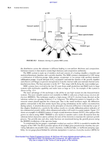
FIGURE 15.3 Schematic drawing of a generic MBE system.
the distribution across the substrate is different leading to non-uniform thickness and composition.
Substrate rotation is then used to ensure high thickness and composition uniformity.
The MBE system is made up of stainless steel and consists of a loading chamber, a transfer and
analytical/treatment chamber, and a growth chamber. The MBE system is maintained in UHV using
a combination of diffusion pumps, turbo pumps, cryopumps, or ion pumps with auxiliary titanium
sublimation pumps. Liquid nitrogen (LN ) cryopanels surround the interior of the growth chamber
2
and effusion cell flanges to prevent reevaporation from the internal walls and maintain thermal isola-
tion between them. The base pressure is in the 10 −11 Torr range with H being the main residual gas.
2
MBE systems have evolved in the last 10 years from small production and R&D tools to large
systems with multiwafer capability and wafer sizes as large as 12 in. An example of this system is
shown in Fig. 15.4.
The main advantage of this technique is the ability to use high vacuum in situ characterization
systems. The most valuable analysis tool available in MBE is reflection of high energy electron dif-
fraction (RHEED). This technique employs a high-energy (20 keV) electron beam, directed on the
substrate surface at a grazing incidence (1 to 3 degrees). The diffraction pattern is imaged on a flu-
orescent screen placed opposite the e-beam gun. Due to the small incidence angle, the diffraction
pattern corresponds to the first atomic layers thus giving information on the surface reconstruction
during epitaxy. A detailed discussion on the principles of electron diffraction is beyond the scope of
this chapter. Qualitatively, a perfectly flat surface results in a streaky diffraction pattern indicative of
two-dimensional growth, while a three-dimensional surface will result in a spotty pattern. Figure 15.5
shows an example of a RHEED pattern of single crystal strontium titanate (SrTiO ) thin epilayer film
3
6
grown on silicon using MBE. RHEED is also useful to monitor native oxide desorption from the
substrate before deposition and to calibrate the ratio of the elements to maintain the optimum growth
process. The growth rates and alloy mole fractions are monitored during the growth process using
the RHEED oscillations of the specular beam.
To complement the ion gauges, a quadruple residual gas analyzer (RGA) is essential to monitor the
integrity of the UHV. The RGA provides spectra of all residual gases present in the chamber, thus pro-
viding indications on possible leaks, system cleanness, insufficient bake, or inefficient pumping capa-
bility. An ion gauge placed behind the substrate manipulator is used as a beam flux monitor (BFM) for
Downloaded from Digital Engineering Library @ McGraw-Hill (www.digitalengineeringlibrary.com)
Copyright © 2004 The McGraw-Hill Companies. All rights reserved.
Any use is subject to the Terms of Use as given at the website.