
Page 224 - Semiconductor Manufacturing Handbook
P. 224
Geng(SMH)_CH15.qxd 04/04/2005 19:53 Page 15.9
EPITAXY
EPITAXY 15.9
Laminar flow Boundary layer
d b
0 x Susceptor
FIGURE 15.8 Boundary layer structure.
The Reynolds number depends on the gas density (ρ), the gas velocity (ν) and gas viscosity (µ).
The boundary layer structure is depicted in Fig. 15.8.
This configuration will retain the flow in the laminar mode, that is, the gas flows in a regular, con-
tinuous, and nonturbulent mode. Yet, the boundary layer thickness is not constant as the gas flow
across the heated wafer surface leading to a nonuniform deposition rate along the flow direction and
in the transverse direction. Therefore, wafer rotation in the azimuthal direction along with a special
injector design for flow distribution control is added to achieve high thickness uniformity. Thorough
treatment of the horizontal reactor process using computational fluid dynamics can be found in
Ref.12 and Ref. 13.
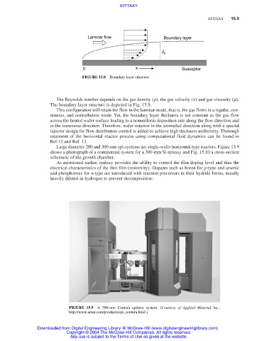
Large diameter 200 and 300 mm epi-systems are single-wafer horizontal type reactors. Figure 15.9
shows a photograph of a commercial system for a 300-mm Si epitaxy and Fig. 15.10 a cross-section
schematic of the growth chamber.
As mentioned earlier, epitaxy provides the ability to control the film doping level and thus the
electrical characteristics of the thin film (resistivity). Dopants such as boron for p-type and arsenic
and phosphorous for n-type are introduced with reaction precursors in their hydride forms, usually
heavily diluted in hydrogen to prevent decomposition:
FIGURE 15.9 A 300-mm Centura epitaxy system. (Courtesy of Applied Material Inc.,
http://www.amat.com/products/epi_centura.html.)
Downloaded from Digital Engineering Library @ McGraw-Hill (www.digitalengineeringlibrary.com)
Copyright © 2004 The McGraw-Hill Companies. All rights reserved.
Any use is subject to the Terms of Use as given at the website.