
Page 222 - Semiconductor Manufacturing Handbook
P. 222
Geng(SMH)_CH15.qxd 04/04/2005 19:53 Page 15.7
EPITAXY
EPITAXY 15.7
This step can described by the following equation:
dh
1 = hC −( C )
g
dt g s
where h is the mass transport factor of the gas in the chamber, and C and C are the concentration
g g s
of the elements in the gas and on the surface.
3. Adsorption of reactants on the surface
4. Surface reactions, which include chemical decomposition, surface migration to nucleation sites,
and incorporation in the lattice
5. Desorption of by-products and transport to the exhaust
Steps 3 through 5 are described by the “over-simplified” equation
dh
2 = kC
dt s s
with k being the surface reaction rate.
s
In steady state
− 1
dh dh k
1 = 2 = H or C = C 1+ s
g
dt dt s k
g
The growth rate is then given by
Gr = H = kh C g = kh C T M
s g
sg
N k s + h N k s + h N
g
g
where N = number of atoms incorporated per unit volume
C = total number of molecules per unit volume in the gas
T
M = mole fraction of the reaction species in the gas
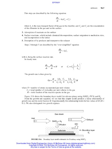
Figure 15.6 shows the boundary-layer model for silicon epitaxy using SiHCl (TCS) and H .
3 2
From the growth rate equation, we see that this simple model predicts a linear relationship of
growth rate and the mole fraction M. Experimentally this relationship holds for low values of M (M <
0.1). We also distinguish two growth regimes:
Gas steam
Inlet
Exhaust
+ H
SiHCl 3 2
Diffusion HCl
Substrate Boundary layer
d b
FIGURE 15.6. Boundary layer model schematic for Si epitaxy using SiHCl .
3
Downloaded from Digital Engineering Library @ McGraw-Hill (www.digitalengineeringlibrary.com)
Copyright © 2004 The McGraw-Hill Companies. All rights reserved.
Any use is subject to the Terms of Use as given at the website.