
Page 246 - Sensing, Intelligence, Motion : How Robots and Humans Move in an Unstructured World
P. 246
DISTINCT KINEMATIC CONFIGURATIONS OF RR ARM 221
x 2
P
x 2
P a 2 l 2
z 1 z o
l 2
y 1
q 2 q 2
J 2
x 1
x 2 x 1
J 2
l 1
z 1
y o l 1
q 1
J 1
x o
J 1
y o
z o
q 1
x o x 1
(a) (b)
z o z 1 x 2
P
x 2
J 1 y o z o z 1
P
l 2
q 1 J 1
x o
a 2
l 1 l 2
a 2 y o
a 1
a 1
q 1
x 1
l 1
q 2 x o
J 2 q 2
J 2
z 2 x 1
x 1
z 2
(c) (d)
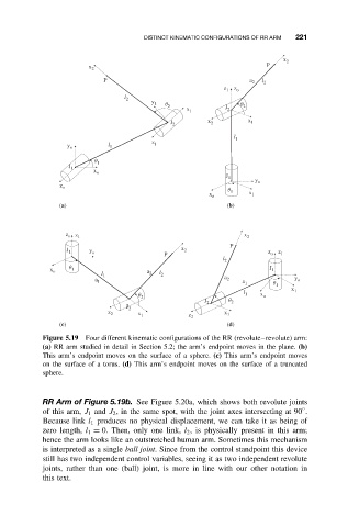
Figure 5.19 Four different kinematic configurations of the RR (revolute–revolute) arm:
(a) RR arm studied in detail in Section 5.2; the arm’s endpoint moves in the plane. (b)
This arm’s endpoint moves on the surface of a sphere. (c) This arm’s endpoint moves
on the surface of a torus. (d) This arm’s endpoint moves on the surface of a truncated
sphere.
RR Arm of Figure 5.19b. See Figure 5.20a, which shows both revolute joints
◦
of this arm, J 1 and J 2 , in the same spot, with the joint axes intersecting at 90 .
Because link l 1 produces no physical displacement, we can take it as being of
zero length, l 1 = 0. Then, only one link, l 2 , is physically present in this arm;
hence the arm looks like an outstretched human arm. Sometimes this mechanism
is interpreted as a single ball joint. Since from the control standpoint this device
still has two independent control variables, seeing it as two independent revolute
joints, rather than one (ball) joint, is more in line with our other notation in
this text.