
Page 340 - Sensors and Control Systems in Manufacturing
P. 340
296
S i x
Cha p te r
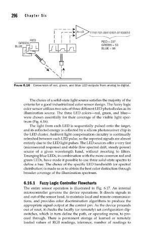
A–>D 11101101-00110101-01100010
RED RED = 237
GREEN
BLUE GREEN = 53
BLUE = 98
FIGURE 6.16 Conversion of red, green, and blue LED outputs from analog to digital.
The choice of a solid-state light source satisfies the majority of the
criteria for a good industrialized color sensor design. The fuzzy logic
color sensor utilizes two sets of three different LED photodiodes as its
illumination source. The three LED colors—red, green, and blue—
were chosen essentially for their coverage of the visible light spec-
trum (Fig. 6.16).
The light from each LED is sequentially pulsed onto the target,
and its reflected energy is collected by a silicon photoreceiver chip in
the LED cluster. Ambient light compensation circuitry is continually
refreshed between each LED pulse, so the reported signals are almost
entirely due to the LED light pulses. The LED sources offer a very fast
(microsecond response) and stable (low spectral drift, steady power)
source of a given wavelength band, without resorting to filters.
Emerging blue LEDs, in combination with the more common red and
green LEDs, have made it possible to use three solid-state spectra to
define a hue. The choice of the specific LED bandwidth (or spectral
distribution) is made so as to obtain the best color distinction through
broader coverage of the illumination spectrum.
6.16.1 Fuzzy Logic Controller Flowcharts
The entire sensor operation is illustrated in Fig. 6.17. An internal
microcontroller governs the device operations. It directs signals in
and out of the sensor head, to maintain local and remote communica-
tions, and provides color discrimination algorithms to produce the
appropriate signal output at the control pin. As the device proceeds
out of reset, it checks the locally (or remotely) set configuration dip-
switches, which in turn define the path, or operating menu, to pro-
ceed through. There is permanent storage of learned or remotely
loaded values of RGB readings, tolerance, number of readings to