Page 507 - Sensors and Control Systems in Manufacturing
P. 507

460
                                    Ni ne
                           Cha p te r


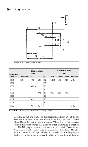
                          FIGURE 9.20  Parts to be turned.


                                                                Switching Data
                                         Displacement
                      Sentence           Data                        Tool
                      Number   Conditions x    y    z    Feed    Speed Tool  Addition
                      N001     G00       X10   Y15  Z2   F1000   S55   T01  M09
                      N002                          Z0
                      N003               X909       Z2
                      N004                          Z0
                      N005                     Y45  Z2   F500    S30   T02
                      N006                          Z0
                      N007               X10        Z2
                      N008                          Z0
                      N009               X0    Y0                           M30

                     TABLE 9.3  NC Program—Automatic Drilling Machine

                          coordinates X20 and Z100. The displacement condition G91 of the sec-
                          ond sentence determines relative addressing (i.e., the x and z values
                          should be added to the previous values). Where the x values are con-
                          cerned, it should be noted that diameter rather than radius is specified.
                             The NC programs shown in these examples must, of course, also
                          be put on a suitable data carrier in machine-readable form. The clas-
                          sic data carrier for NC is punched tape. Each character in the program
                          text is converted into a 7-bit combination of 1s and 0s and stamped
   502   503   504   505   506   507   508   509   510   511   512