
Page 509 - Sensors and Control Systems in Manufacturing
P. 509
462
Cha p te r
Ni ne
media such as floppy disks are used more and more. It is also possible
to use an economical personal computer as a development and docu-
mentation station for NC programs.
9.6.5 Operation of an NC System
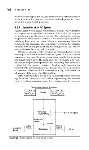
Figure 9.22 is a block diagram of a simple NC system. The NC machine
is equipped with a punched tape reader into which the program
for machining a specific piece is inserted. After starting the program,
the processor reads the first sentence. The various displacement and
switching data are written into a reference-value memory. Next, the
commands are processed. The comparator compares the reference
values to the values supplied by the measuring devices (e.g., the cur-
rent positions of the x- and y-drive units).
If there is a difference between reference values and actual values,
the comparator generates suitable control signals for the final control
elements of the drives. These are generated only until reference values
and actual values agree. The comparator now demands a new sen-
tence from the punched tape reader for processing. This sentence is
evaluated in the manner described. Reading and processing are
repeated until the final sentence has been processed. As an example
of reference value/actual value comparison, Fig. 9.23 shows the
adjustment of the x axis of an NC machine.
If the machine slide is moved from its current position represent-
ing the actual value to a new position representing the reference
value, a continuous comparison of the reference value to the actual
FIGURE 9.22 Block diagram for a simple NC system.