
Page 508 - Sensors and Control Systems in Manufacturing
P. 508
Communications
Switching Data 461
Displacement
Data Tool
Sentence
Number Conditions x y z Feed Speed Tool Addition
N001 G01 X20 Z100 F1500 S60 T03 M09
N002 G91 Z–30
N003 X + 20
N004 X + 10 Z–30
N005 X + 30
N006 Z–40 M30
TABLE 9.4 NC Program—Lathe Machining Operation
into the tape as an appropriate combination of holes and spaces (1 =
hole, 0 = no hole).
This process of conversion is called coding. The totality of all com-
binations of holes representing a character set is called a code.
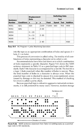
Recommendations have been laid down as to which combination
of holes represents a specific character. Figure 9.21 shows the N005
sentence statement in Table 9.3 as a punched tape code to ISO stan-
dards. Each 7-bit character is accompanied by a test bit. The test bit is
a logic 1 (hole punched) when the number of holes is uneven. Thus,
the total number of holes in a character is always even. When the
punched tape code is checked to ensure it is even-numbered, errors
caused by damage or dirt may be detected. This method of checking
for errors is called a parity check.
Because punched tape is robust in aggressive industrial environ-
ments, it is still preferred by many users. However, modern storage
FIGURE 9.21 N005 sentence statement from Table 9.3 (drilling task) as a punched
tape code to ISO standards.