
Page 511 - Sensors and Control Systems in Manufacturing
P. 511
464
Ni ne
Cha p te r
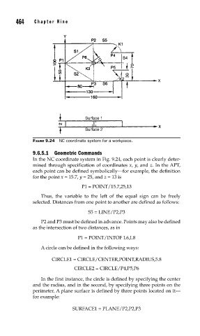
FIGURE 9.24 NC coordinate system for a workpiece.
9.6.5.1 Geometric Commands
In the NC coordinate system in Fig. 9.24, each point is clearly deter-
mined through specification of coordinates x, y, and z. In the APT,
each point can be defined symbolically—for example, the definition
for the point x = 15.7, y = 25, and z = 13 is
P1 = POINT/15.7,25,13
Thus, the variable to the left of the equal sign can be freely
selected. Distances from one point to another are defined as follows:
S5 = LINE/P2,P3
P2 and P3 must be defined in advance. Points may also be defined
as the intersection of two distances, as in
P1 = POINT/INTOF L6,L8
A circle can be defined in the following ways:
CIRCLE1 = CIRCLE/CENTER,POINT,RADIUS,5.8
CIRCLE2 = CIRCLE/P4,P5,P6
In the first instance, the circle is defined by specifying the center
and the radius, and in the second, by specifying three points on the
perimeter. A plane surface is defined by three points located on it—
for example:
SURFACE1 = PLANE/P2,P2,P3