Page 552 - Sensors and Control Systems in Manufacturing
P. 552
SpectRx NIR Technology
                          and tilt of the recombining wavefronts. Modulation due solely to the   505
                          imperfections of the beam-splitter is given by:

                                                σ
                                                        σ
                                                             σ
                                            M () = 4 r ()⋅ t ()               (10.28)
                                              BS     BS    BS
                          where  M  = beam-splitter modulation
                                   BS
                                  r  = beam-splitter reflectivity
                                   BS
                                  t  = beam-splitter transmissivity
                                   BS
                             Maximum beam-splitter modulation (i.e., M BS  = 1) occurs when
                          r  and t  are equal to 0.5.
                           BS    BS
                             The typical interferometer modulation for input port A is 70 per-
                          cent using five-second precision corner-cube retroreflectors. Better
                          modulation can be expected with the use of one-second precision ret-
                          roreflectors.
                             It should be noted that the total energy is split between the two
                          output ports. This factor is normally included in the instrument
                          efficiency  ξ together with beam-splitter modulation and system
                          transmission.
                                                    σ ⋅ M
                                                ξ =  T()  BS                  (10.29)
                                                      2
                             Input port B can be set to look at a cold source to reduce the pho-
                          ton noise.

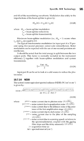
                          10.7.14 NESR
                                                                             2
                          The system’s noise equivalent spectral radiance (NESR) (W/cm  sr cm )
                                                                                  –1
                          is given by:
                                                                  )
                                                  )
                                                          ) + (I
                                   (( I  photon 2  +  I (  quantization 2  +  I (  darknoise 2  Johnson 2  + (I  jitter 2  + (I  scan.inst 2
                                                                                ) )
                                                                        )
                                        )
                            NESR =
                                                  Δσ  ⋅ Θ ξ     ⋅ F
                                                       ⋅ ⋅ t ⋅ R()σ
                                                                              (10.30)
                          where     I  photon  = noise current due to photon noise  (/A  Hz )
                                  I quantization  =  noise current due to quantization noise  (/A  Hz )
                                    I  Johnson  =  noise current due to the Johnson noise of the resis-
                                           tance of the first amplification stage (/A  Hz )
                                   I  darknoise  = noise current due to dark noise (/A  Hz )
                                      I  jitter  =  noise current due to the jitter of the sampling
                                            A
                                           (/ Hz  )
                                   I  scan. inst.  =  noise current due to scanning speed variations in
                                           the spectroradiometer, coupled with the analog
                                           filter slope and the delay mismatch  (/A  Hz )
                                        t = acquisition time (s)
                                                            –1
                                       Δσ = spectral interval (cm )

