
Page 194 - Standard Handbook Of Petroleum & Natural Gas Engineering
P. 194
Fluid Mechanics 179
4
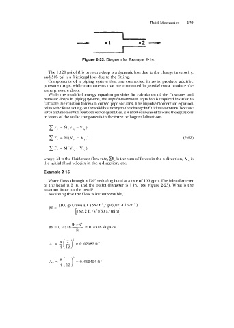
Figure 2-22. Diagram for Example 2-14.
The 1,120 psi of this pressure drop is a dynamic loss due to the change in velocity,
and 505 psi is a frictional loss due to the fitting.
Components of a piping system that are connected in series produce additive
pressure drops, while components that are connected in parallel must produce the
same pressure drop.
While the modified energy equation provides for calculation of the flowrates and
pressure drops in piping systems, the impulse-momentum equation is required in order to
calculate the reaction forces on curved pipe sections. The impulse-momentum equation
relates the force acting on the solid boundary to the change in fluid momentum. Because
force and momentum are bothvector quantities, it is most convenient to write the equations
in terms of the scalar components in the three orthogonal directions.
(2-62)
where M is the fluid mass flow rate, ZFx is the sum of forces in the x direction, v, is
the initial fluid velocity in the x direction, etc.
Example 2-1 5
Water flows through a 120" reducing bend at a rate of 100 gpm. The inlet diameter
of the bend is 2 in. and the outlet diameter is 1 in. (see Figure 2-23). What is the
reaction force on the bend?
Assuming that the flow is incompressible,
h;l= (100 gal/min)(0.1337 ft3/ga1)(62.4 lb/ft')
[(32.2 ft/s2)(60 s/min)]
Ib - s4
M = 0.4318- = 0.4318 slugs/s
ft
A = "( 2)' 0.02182 ft2
=
' 4 12
12
A = E(L)' = 0.005454ft2
4