
Page 260 - Sustainability in the Process Industry Integration and Optimization
P. 260
E x a m p l e s a n d Ca s e S t u d i e s 237
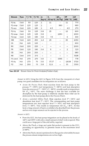
Stream Type T [°C] T [°C] m C ΔH CP ΔH
s t p vap
[kg/s] [kJ/kg·°C] [kJ/kg] [kW/°C] [kW]
F1-liq Cold 50 120 1 11 — 11 770
F1-evap Сold 120 120 1 — 990 — 990
F1-vap Сold 120 180 1 4.5 — 4.5 270
F2-liq Cold 50 125 0.8 15 — 12 900
F2-evap Cold 125 125 0.8 — 1250 — 1000
F2-vap Cold 125 180 0.8 7.5 — 6 330
HM Cold 220 250 1.4 25 — 35 1050
CA Hot 120 120 — — — — 900
RA Cold 220 220 — — — — 1000
FR Cold 120 180 0.4 5 — 2 120
CB Hot 200 200 — — — — 980
RB Cold 270 270 — — — — 1928
P1-cond Hot 270 270 0.5 — 1556 — 778
P1-liq Hot 270 70 0.5 37.17 — 18.58 3716
P2 Hot 200 70 0.8 12.5 — 10 1300
TABLE 10.14 Stream Data for Pinch Analysis [Problem 5(a)].
Answer to (d)(1). Using the GCC in Figure 10.19, from the viewpoint of a heat
pump, two good candidates for its integration are as follows:
• Across the Process Pinch. Heat rejection from the heat pump to the
process T* = 230°C (real temperature T = 240°C) and heat absorption
from the process at T* = 190°C (T = 180°C), would result in temperature
lift ΔT = 60°C. The main challenge is that the heat available for
lift
absorption by the heat pump is relatively smaller than what can be
delivered by the heat pump above the Process Pinch.
• Across a potential Utility Pinch. Heat rejection level T* = 130°C and
absorbtion heat level T* = 110°C. The corresponding real heat pump
temperatures are: heat rejection level T = 140°C and heat absorption
level, T = 100°C. This results in temperature lift ΔT = 40°C. At this
lift
level, a large amount of heat is available to be absorbed from the process
and an even larger amount can be rejected to the process.
Answer to (d)(2).
• From the GCC, the heat pump integration can be placed at the levels of
140°C and 100°C with only a small amount of shaft work required. This
could save a large part of the cold utility required.
• Above the Pinch, a large and quite flat pocket is present in the CCC,
providing an opportunity to generate steam at the maximum level
of 180°C.
• Above the Pinch, steam is preferred over flue gas for a hot utility because
the process stream temperatures are not too high.