
Page 263 - Sustainability in the Process Industry Integration and Optimization
P. 263
240 Cha p te r T e n
Problem 6: Solutions
Answer to (a). Table 10.17 shows the missing parameters of process streams
described in Table 10.15.
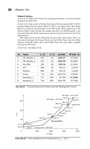
Answer to (b). There are two Pinches: the Process Pinch (located at 132°C/122°C)
and the Utility Pinch (located at 260.1°C/250.1°C; see Figure 10.21. The Utility
Pinch is caused by the placement of the MP steam. More significant is the
Process Pinch, which divides the design area into two different parts: a net
heat sink above the Pinch temperatures and a net heat source below the Pinch
temperatures.
The Utility Pinch further subdivides the area above the Process Pinch. In
the interval between the Process Pinch and the Utility Pinch, the only utility
allowed is the MP steam. Above the Utility Pinch, the only utility available
remains the HP steam.
Answer to (c). See Figure 10.22.
No Name T [°C] T [°C] ΔH [kW] CP [kW/°C]
s t
1 OH_Naphta_1 100 41 1623.17 27.5113
2 OH_Naphta_2 132 60 1669.32 23.1850
3 OH_HKD 224 65 1787.16 11.2400
4 LCT 268 30 363.12 1.5257
5 Residue 283 45 336.25 1.4128
6 Crude 30 146 2031.50 17.5132
7 Denaphta_1 117 204 977.88 11.2400
8 Denaphta_2 176 305 1641.45 12.7244
TABLE 10.17 Process Streams for Problem 6(a) with Missing Data Filled In
HP steam = 654.2 kW
320.0°C 320.1°C
MP steam = 874.4 kW
300 305.0°C
260.1°C
260.0°C
Utility Pinch
224.0°C 250.1°C
200
204.0°C
T [°C] 132.0°C 146.0°C
176.0°C
100.0°C 122.0°C
100
Process Pinch
45.0°C
41.0°C 60.0°C
30.0°C
20.0°C Cooling water = 2657 kW
0 2000 4000 6000 8000
ΔH [kW]
FIGURE 10.21 Pinch identifi cation for Problem 6(b), ΔT = 10°C.
min