
Page 104 - The Art and Science of Analog Circuit Design
P. 104
William H. Gross
gone. Although I have seen some products recently that appear to be
solutions looking for problems!
This is not to say that you need marketing surveys with lots of paper-
work and calculations on a spreadsheet. These things are often man-
agement methods to define responsibility and place blame. It is my
experience that the errors in these forms are always in the estimate of the
selling price and the size of the market. These inputs usually come from
marketing and maybe that is why there is such a high turnover of person-
nel in semiconductor marketing departments. After all, if the marketers
who made the estimates change jobs every three years, no one will ever
catch up with them. This is because it typically takes two years for devel-
opment and two more years to see if the product meets its sales goals.
So with almost no official marketing input, but based on conversations
with many people over several years, I began the definition of a new
product. I felt there was a market for an 1C video fader and that the mar-
ket was going to grow significantly over the next five years. The driving
force behind this growth would be PC based multi-media systems. At the
same time I recognized that a fader with only one input driven is a very
good adjustable gain amplifier and that is a very versatile analog building
block. The main source of this market information was conversations
with customers trying to use a transconductance amplifier that I had de-
signed several years earlier in fader and gain control applications.
The Video Fader
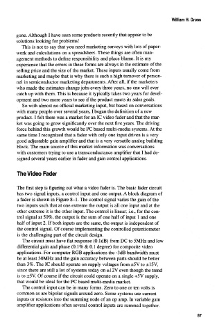
The first step is figuring out what a video fader is. The basic fader circuit
has two signal inputs, a control input and one output. A block diagram of
a fader is shown in Figure 8-1. The control signal varies the gain of the
two inputs such that at one extreme the output is all one input and at the
other extreme it is the other input. The control is linear; i.e., for the con-
trol signal at 50%, the output is the sum of one half of input 1 and one
half of input 2. If both inputs are the same, the output is independent of
the control signal. Of course implementing the controlled potentiometer
is the challenging part of the circuit design.
The circuit must have flat response (O.ldB) from DC to 5MHz and low
differential gain and phase (0.1% & 0.1 degree) for composite video
applications. For computer RGB applications the -3dB bandwidth must
be at least 30MHz and the gain accuracy between parts should be better
than 3%. The 1C should operate on supply voltages from ±5V to ±15V,
since there are still a lot of systems today on ±12V even though the trend
Is to ±5 V. Of course if the circuit could operate on a single +5 V supply,
that would be ideal for the PC based multi-media market.
The control input can be in many forms. Zero to one or ten volts is
common as are bipolar signals around zero. Some systems use current
inputs or resistors into the summing node of an op amp. In variable gain
amplifier applications often several control inputs are summed together.
87