
Page 105 - The Art and Science of Analog Circuit Design
P. 105
One Trip Down the 1C Development Road
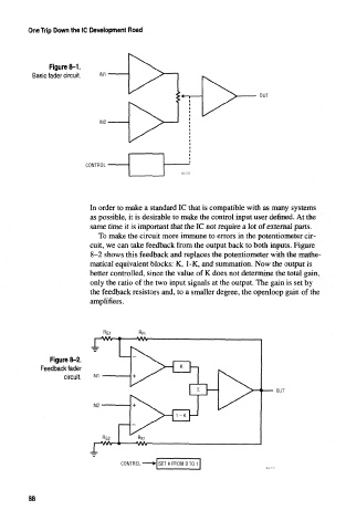
Figure 8-1.
Basic fader circuit,
OUT
CONTROL
In order to make a standard 1C that is compatible with as many systems
as possible, it is desirable to make the control input user defined. At the
same time it is important that the 1C not require a lot of external parts,
To make the circuit more immune to errors in the potentiometer cir-
cuit, we can take feedback from the output back to both inputs. Figure
8-2 shows this feedback and replaces the potentiometer with the mathe-
matical equivalent blocks: K, 1-K, and summation. Now the output is
better controlled, since the value of K does not determine the total gain,
only the ratio of the two input signals at the output. The gain is set by
the feedback resistors and, to a smaller degree, the openloop gain of the
amplifiers.
• u i
i—VW—«>
Figure 8-2.
Feedback fader
circuit. im
OUT
r-AAA>—*
CONTROL H SET K FROM 0 TO 1
88