
Page 106 - The Art and Science of Analog Circuit Design
P. 106
William H. Gross
Circuits
At this point it is time to look at some actual circuits. Do we use voltage
feedback or current feedback? Since the current feedback topology has
Inherently better linearity and transient response, it seemed a natural for
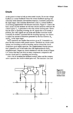
the input stages. One customer showed me a class A, current feedback
circuit being implemented with discrete transistors. Figure 8-3 shows the
basic circuit. For the moment we will not concern ourselves with how the
control signal, V c, is generated to drive the current steering pairs. Notice
that the fader is operating inverting; for AC signals this is not usually a
problem, but video signals are uni-polar and another inversion would
eventually be needed. I assumed that the inverting topology was chosen
to reduce the amount of distortion generated by the bias resistors, R B1
and R B2» in the input stages.
Since transistors are smaller than resistors in an 1C, I intended to re-
place the bias resistors with current sources. Therefore my circuit could
operate non-inverting as well as inverting, and as a bonus the circuit
would have good supply rejection. The complementary bipolar process
that I planned to use would make class AB implementations fairly
straightforward. I began my circuit simulations with the circuit of Figure
8-4; notice that there are twice as many components compared to the
discrete circuit and it is operating non-inverting.
After a bit of tweaking the feedback resistor values and the compen-
sation capacitor, the circuit worked quite well. The transistor sizes and
Figure 8-3.
Discrete design,
class A current
feedback fader,
OUT
89