
Page 107 - The Art and Science of Analog Circuit Design
P. 107
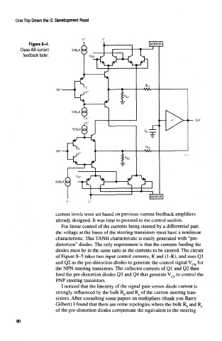
One Trip Down the 1C Development Road


              Figure 8-4.
           Class AB current
            feedback fader.


                          SOOjaA


                          current levels were set based on previous current feedback amplifiers
                          already designed. It was time to proceed to the control section.
                            For linear control of the currents being steered by a differential pair,
                          the voltage at the bases of the steering transistors must have a nonlinear
                          characteristic. This TANK characteristic is easily generated with "pre-
                          distortion" diodes. The only requirement is that the currents feeding the
                          diodes must be in the same ratio as the currents to be steered. The ckcuit
                          of Figure 8-5 takes two input control currents, K and (1-K), and uses Ql
                          and Q2 as the pre-distortion diodes to generate the control signal V CN for
                          the NPN steering transistors. The collector currents of Ql and Q2 then
                          feed the pre-distortion diodes Q3 and Q4 that generate V cp to control the
                          PNP steering transistors.
                            I noticed that the linearity of the signal gain versus diode current is
                          strongly influenced by the bulk R b and R e of the current steering tran-
                          sistors. After consulting some papers on multipliers (thank you Barry
                          Gilbert) I found that there are some topologies where the bulk R^ and R e
                          of the pre-distortion diodes compensate the equivalent in the steering

         90