
Page 108 - The Art and Science of Analog Circuit Design
P. 108
William H, Gross
TO MIRROR Figure 8-5.
Basic circuit to
drive the steering
transistors.
BIAS
TO MIRROR
transistors. Unfortunately, in my circuit I am using PNPs to drive NPNs
and vice versa. In order to match the pre-distortion diodes to the steering
transistors, a more complicated circuit was required. I spent a little time
and added a lot more transistors to come up with a circuit where the
pre-distortion diodes for the NPN steering transistors were NPNs, and
the same for the PNPs. Imagine my surprise when it didn't solve the lin-
earity problem. I have not included this circuit because I don't remember
it; after all, it didn't work.
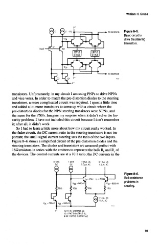
So I had to learn a little more about how my circuit really worked. In
the fader circuit, the DC current ratio in the steering transistors is not im-
portant; the small signal current steering sets the ratio of the two inputs.
Figure 8-6 shows a simplified circuit of the pre-distortion diodes and the
steering transistors. The diodes and transistors are assumed perfect with
ISO resistors in series with the emitters to represent the bulk R b and R e of
the devices. The control currents are at a 10:1 ratio; the DC currents in the
0.1mA 1.0mA, DC 0.1mA, DC
DC 9.5|aA, AC 1.5uA, AC
Figure 8-6.
Bulk resistance
problems in
= 600mV
steering.
10:1 RATIO INPUT DC
10:1 RATIO OUTPUT DC
6.33:1 RATIO OUTPUT AC
91