Page 127 - The Geological Interpretation of Well Logs
P. 127

-  THE  DENSITY  AND  PHOTOELECTRIC  FACTOR  LOGS  -

        Table  9.2  Density,  electron  density  and  tool  given  density  for  some  common  compounds  (from  Schlumberger,  1989a).

        Compound         Formula          Actual  density        Tool  density  based  on   *Density  given  on
                                          p,,  g/cm?             electron  density  (pe),  g/cm  ~—  log  g/cm?

        Quartz          SiO,              2.654                  2.650                  2.648
       Calcite           Caco,            2.710                  2.708                  2.710
        Dolomite         CaCO,MgCO,       2.850                  2.863                  2.850

       Halite            NaCl             2.165                  2.074                  2.032
       Gypsum            CaSO,2H,0        2.320                  2.372                  2.381
       Anhydrite         CaSO,            2.960                  2.957                  2.977
        Sylvite          KCI.             1.984                  1.916                  1.863

        Coal  bituminous                  1.200                  1.272                  1.173
                                          1.500                  1.590                  1.514
        Coal  anthracite                  1.400                  1.442                  1.355
                                          1.800                  1.852                  1.796

        Fresh  water     H,O              1.000                  1.110                  {.000
        Salt  water      200,000  ppm     1.146                  1.273                  1.135
        Oit              n(CH,)           0.850                  0.970                  0.850
       Methane           CH,              0.000677               0.00084
       Gas               C,  Ay,          0.000773               0.00096

        *Density  given  on  log  =  1.0704  (pe)  —  0.1883


                         .                                              TOOL
        Table  9.3  Moder  density  tools,
        1,  Density  measurement                                      f  y

        Name               Symbol   Company
                                                                       GAMMA  RAY

        Formation  Density                                         -
        Compensated        FDC      Schlumberger                     rr                      SOL  HEAD
        Compensated  Densilog   CDL   Western  Atlas,  Halliburton    HO                    ‘e chematic)
        Compensated  Density   CDS   BPB

        2.  Density  and  Photoelectric  measurement

        Name               Symbol   Company
                                                              GAMMA  Ray

        Litho-Density  Tool   LOT   Schlumberger            ee  303m)
        Compensated  Z-Density  ZDL   Western  Atlas
        Photoelectric  Density   PDS   BPB                              compensated
        Spectral  Density  Toot   HSDL   Halliburton                    W338  wm}
                                                                                 long  spacing

                                                                                   detector


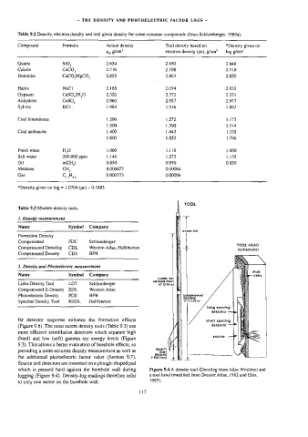
        far  detector  response  enhance  the  formation  effects               short  spacing
        (Figure  9.6).  The  most  recent  density  tools  (Table  9.3)  use       detector
        more  efficient  scintillation  detectors  which  separate  high
        (hard)  and  low  (soft)  gamma  ray  energy  levels  (Figure              source
        9.3).  This  allows  a  better  evaluation  of  borehole  effects,  so
        providing  a  more  accurate  density  measurement  as  well  as   OE ONY
        the  additional  photoelectric  factor  value  (Section  9.7).   x flea gem)   77
        Source  and  detectors  are  mounted  on  a  plough-shaped  pad
        which  is  pressed  hard  against  the  borehole  wall  during   Figure  9.4  A  density  tool  (Densilog  from  Atlas  Wireline)  and
        logging  (Figure  9.4).  Density-log  readings  therefore  refer   a  tool  head  (modified  frorn  Dresser  Atlas,  1982  and  Ellis,
                                                           1987).
        to  only  one  sector  on  the  borehole  wall.
                                                       117
   122   123   124   125   126   127   128   129   130   131   132