
Page 232 - The Geological Interpretation of Well Logs
P. 232
- THE GEOLOGICAL INTERPRETATION OF WELL LOGS -
way, fracture infill may be plucked out during drilling in measured. Adding flowmeter readings allows the flowing
the immediate vicinity of the borehole and the walls of fractures to be separated from the non-flowing ones:
the fractures broken, so enlarging the aperture. essential information (Figure 13.32).
Separating drilling induced from natura] fractures is
notoriously difficult. On cores, distinctive geometry and - borehole breakouts
surface features are used (Kulander ef ad, 1990). In the Because of its sensitivity to borehole geometry, the
subsurface. a combination of geometry and orientation can BHTY is an excellent indicator of breakouts (Chapter 4).
be used (Table 13.5, Figure 13.31) (Lincecum e7 al., 1993). Breakouts are marked by hole enlargement in the direc-
For example, most drilling induced fractures form paraile] tion of minimum horizontal stress, Sh_,. Enlargement
to the maximum horizontal stress direction Sh,,,, which is seen on the amplitude image log and the time of flight
means that they are extensional fractures. The Sh,,, orien- log as vertical strips indicating poor reflectivity and long
tations are well identified from breakouts (see below) and travel time or lost signal (Figure 13.33) (Paillet and Kim,
may be used to define preferred fracture orientation (Figure 1987). In addition to the images, the acoustic caliper
13.31). Apart from this, induced fractures, of course, are derived from the time of flight measurements, can be used
never mineralised and never cause bedding offset. For nat- to indicate the hole circumference profile (Figure 13.33).
ural fracture classification, the important distinctions other As discussed above, the use of breakouts to derive
than onentation are whether the feature is open or closed or present day in situ stress orientations, is an important
mineralised. As described (Section 13.7) comparisons phase in the attempt to separate natural from drilling
between amplitude and time of flight images can suggest induced fractures. Although dipmeter calipers are tradi-
whether a fracture is open or mineralised, open fractures tionally used for breakout analysis (Chapter 4), when
having an image on both logs, mineralised fractures on BHTY images are available they are far more effective
only the amplitude image (Taylor, 1991). and more precise.
Despite al] the difficulties, fracture studies with
acoustic images make a significant contribution to reser- — texture, lithology & sedimentary features
voir understanding. This is well illustrated by the USGS For lithological features to be seen on the acoustic
technique of combining image studies with high quality images, there must be large acoustic impedance contrasts.
flowmeter measurements (Paillet ef ai, 1987; Paillet, The coal industry has long used the BHTV to localise
1991). It is well known in aquifer studies that major flow coal seams and give accurate bed limits (e.g. Riibel er al.,
is usually from only a few fractures. Using the BHTV 1986). However, coal seams are an exception in terms of
allows major fractures to be located and their orjentations lithology and more general lithological investigations
dipping fracture
BHTV
FARM
exaggerated
width
exaggerated
width
T
N
T
T
S
Ww
E
N
s
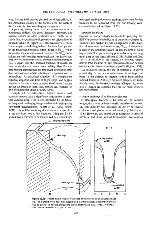
Figure 13.30 Typical characteristics of an open fracture seen on an acoustic image
log. The fracture width becomes exaggerated at certain points around the borehole
wall as a result of drilling damage (re-drawn from Paillet et al., 1985). Note this
effect on the fractures of Figure 13.28.