
Page 227 - The Geological Interpretation of Well Logs
P. 227
- IMAGE LOGS ~
TELEMETRY
flux-gate
magnetometer
SPECTRALOG
ORIENTATION
a
Dn
2 ELE CTRONICS
NI
£
fs
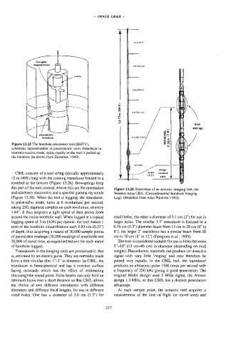
Figure 13.25 The borehole televiewer tool (BHTY), springs
N
transducers
=
bow
(7°6'}
MANDREL
piezoelectric
schematic representation. A piezoelectric sonic transducer in 2:32m /
lransmit-receive mode, spins rapidly as the tool is pulled up
the borehole (re-drawn from Zemanek, 1969).
imaga
0-4m
CBIL consists of a tool string typically approximately
measure
11-37)
{2 m (40ft) long with the rotating transducer housed in a point
mandrel at the bottom (Figure 13.26). Bowsprings keep
this part of the tool centred. Above this are the orientation
Figure 13.26 Illustration of an acoustic imaging tool, the
and telemetry electronics and a spectral gamma ray sonde Western Atlas CBIL (Circumferential Borehole Imaging
(Figure 13.26). When the tool is logging, the transducer, Log). (Modified from Atlas Wireline, 1992).
in pulse-echo mode, tums at 6 revolutions per second,
taking 250, digitised samples on each revolution, or every
144°. It thus acquires @ tight spiral of data points from
around the entire borehole wall. When logged at a typical small holes, the other a diameter of 5.1 cm (2”) for use in
logging speed of 3 m (10ft) per minute, the too] makes | larger holes. The smaller 1.5” transducer is focused to a
scan of the borehole circumference each 0.83 cm (0.33) 0.76 cm (G@.3") diameter beam fram 15 cm to 20 cm (6" to
of depth, thus acquiring a matrix of 30,000 sample points 8"); the larger 2” transducer has a similar beam from 20
of paired data readings (30,000 readings of amplitude and em to 30 cm (8" to 12") (Faraguna er al., 1989).
30,000 of travel time, as explained below) for each metre The tool is considered suitable for use in holes between
of borehole logged. 5°-18" (13 em—46 cm) in diameter (depending on mud
Transducers in the tmaging tools are piezoelectric, that weight). Piezoelectric materials can produce (or detect) a
is, activated by an electric pulse. They are normally made signal with very little ‘ringing’ and may therefore be
from a thin circular disc 1"—2” in diameter. In CBIL, the pulsed very rapidly. In the CBIL tool, the transducer
transducer is hemispherica) and has a concave surface produces an ultrasonic pulse 1500 times per second with
facing outwards which has the effect of collimating a frequency of 250 kHz giving it good penetration. The
(focusing) the sound pulse. Pulse beams can only hold an original Mobil design used 2 MHz signal, the Amoco
optimum focus over a short distance so that CBIL allows design 1.3 MHz, so that CBIL has a distinct penetration
the choice of two different wansducers with different advantage.
diameters and different focal lengths, for use in different At each sample point, the acoustic tool acquires a
sized holes. One has a diameter of 3.8 cm (1.5") for 217 measurement of the time of flight (or travel Gme) and