
Page 224 - The Geological Interpretation of Well Logs
P. 224
- THE GEOLOGICAL INTERPRETATION OF WELL LOGS -
to cave (cf. Figure 12.38) so that images are of poor
quality.
— shenps
2895.9 If definitions are to be followed strictly, then slumps are
a sedimentary feature. However, following a definition
, complex for a definition’s sake is an Anglo-Saxon failing. Slumps
fractures
are considered here as illustrating fold aspects on the
images and, indirectly, the aspect of non-linear features
in general. Slumping involves both folds and faults at a
small seale. A slump fold will be used here as a example.
The image (Figure 13.23) is of a slumped chalk interval.
Slumped chalks are common in the area but the image is
taken from a bed which, on the standard logs, simply
appears as a carbonate interval in a shale to mar] section,
Clearly the carbonate was nol deposited in place and has
slumped from a nearby source. The structure is a recum-
bent fold with an east to west fold axis and recumbent
(i.e. closed) to the west (Figure 13.23), this being the
direction of down-slope movement,
2ASG.
ACQUISITION
2896 .! 100’
IMAGES
CURVES
m taller speed correction) PROCESSED O
Resistive
depth incr Resist. Conductive li
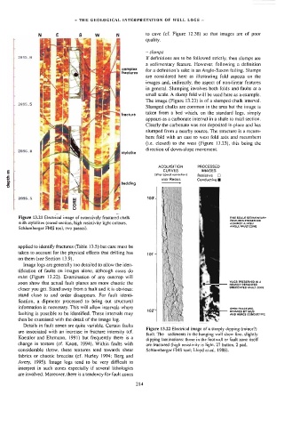
Figure 13.21 Electrical image of extensively fractured chalk FINE SCALE SEDIMENTARY
FEATURES PRESERVED
with stylolites (cored section, high resistivity light colours, AGAINST A HIGH
ANGLE FAULT ZONE
Schlumberger FMS tool. two passes).
applied to identify fractures (Table 13.5) but care must be
takeo to account for the physical effects that drilling has
on them (see Section 13.9).
Image logs are generally too detailed to allow the iden-
tification of faults on images alone, although cases do
exist (Figure 13,22). Examination of any outcrop will
VUGS PRESERVEO IN A
soon show that actual fault planes are more chaotic the
HEAVILY CEMENTED
then be examined with the detail of the image log. OPEN FRACTORE,
BRECCIATED FAULT ZONE
closer you get. Stand away from a fault and it is obvious:
stand close to and order disappears. For fault identi-
fication, a dipmeter processed to bring out structural
information is necessary. This will allow intervals where
102‘
INVADEO BY MUD
faulting is possible to be identified. These intervals may
AND HENCE CONDUCTIVE
Details in fault zones are quite variable. Certain faults
Figure 13.22 Electrical image of a steeply dipping (minor?)
are associated with an increase in fracture intensity (cf.
fault. The sediments in the hanging wall show fine, slightly
Koestler and Ehrmann, 199)) but frequently there is a
dipping laminations: those in the footwall or fault zone ilself
change in texture (cf. Knott, ]994), Within faults with are fractured (high resislivity is light, 27 button, 2 pad,
considerable throw, these textures tend towards shear Schlumberger FMS tool; Lloyd ei a/., 1986).
fabrics or chaotic breccias (cf. Hurley 1994; Berg and
Avery, 1995). Image logs tend to be very difficult to
interpret in such zones especially if several lithologies
are involved. Moreover, there is a tendency for fault zones
214