
Page 64 - The Geological Interpretation of Well Logs
P. 64
- THE GEOLOGICAL INTERPRETATION OF WELL LOGS -
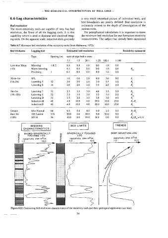
6.6 Log characteristics a very much smoothed picture of individual beds, and
bed boundaries are poorly defined. Bed resolution is
Bed resolution intimately related to the depth of investigation of the
The micro-resistivity tools are capable of very fine bed various tools.
resolution, the finest of all the logging tools. [t is this For petrophysical calculations it is important to know
capability which is used in dipmeter and electrical imag- the minimum bed resolution for true formation resistivity
ing tools. On the opposite scale, induction tools give only measurements. The subject has already been mentioned
Table 6.7 Minimum bed resolution of the resistivicy tools (from Hartmann, 1975).
Bed thickness Logging tool Estimated bed resolution Resistivity measured
Type Spacing (in) _ ratio of edge bed to zone
5:1 1:5 20:1 1:20 100:1 1:100
Less than 30cm = =—Ss Microlog 1&2 0.5 0.0 1.0 0.0 1.0 0.0
(Le) Micro-laterolog 0.3 0.0 0.5 0.0 1.0 0.0 R,,
Proximity ] 0.3 0.0 0.5 0.0 1.0 0.0
30cm-Im SFL 1,0 0.0 2.0 0.0 3.0 0.0 R
(i ft-3ft) Laterolog 3 12 2.0 2.0 2.0 3.0 2.5 4.0 R
Laterolog 8 14 2.0 2.0 2.0 3.0 2.5 4.0 R,
I1m-3m Laterolog 7 32 2.5 3.5 3.0 4.0 3.5 5.0 R,
(3ft-10ft) Laterolog $ 32 2.5 3.0 3.0 3.5 3.0 5.0 R
Laterolog D 32 2.5 3.0 3.0 3.5 3.0 4.0 R,
Induction M 40 4.0 10.0 4.0 20.0 10.0 25.0 R-R,
Induction D 40 4.0 10.0 4.0 20.0 10.0 25.0 R,
Greater 64in Normal 64 6.0 0.0 8.0 0.0 1.0 0.0 R-R,
than 3m 18ft Lateral 216 20.0 0.0 30.0 0.0 50.0 0.0 R,
(10ft) SN 16 16 10.0 6.0 20.0 10.0 0.0 0.0 R(R,, = 9.1)
9 2 > SPHERICALLY FOCUSED DEEP INDUCTION LOG
TRENOS
BED LIMITS
BEDDING
CHARACTERISTICS
MICRO-SPHERIGALLY
~
5
a
5
2
FOCUSED LOG
LOG
resistivity ohm m2/m
ohm m2/m
"6
00
istivity
100
res stivity o
isti
2;
tei ohm mo
° £
Figure 6.21 Contrasting bed resolution characteristics of the resistivity tools and their geological application (see text).
54