
Page 61 - The Geological Interpretation of Well Logs
P. 61
~ RESISTIVITY AND CONDUCTIVITY LOGS -
Resistivity tools exist with diverse capabilities as a
result of the need to measure formation resistivity from
anywhere between the immediate vicinity of the borehole
wall and the flushed zone, to the distant, uninvaded
formation (Figure 6.18). The deeper looking devices are
hole-centred (Figure 6.16) while the shallow investigat-
ing devices, like the microlog, are mounted on a pad
measured depth of investigation usually refers to the
eaulpotential surfaces ” pressed against the borehole wall (Table 6.6, Figure
6.17). It should be noted here that in the literature,
NON-FOCUSED FOCUSED detection of 50% of the emitted signal.
In the modern logging suite, the focused laterologs are
Figure 6.15 Schematic drawing of focused and non-focused the deepest ‘locking’ and most likely to give the virgin
electrical current distribution about a logging too]. The old formation resistivity, R.. Slightly shallower, invaded
Electrical Survey tools were not focused: modem Laterologs
zone resistivities, R,, are measured by shallow focused
are focused.
faterologs and body mounted devices such as the SFL. All
LATEROLOG 3 LATEROLOG 7 DUAL LATEROLOGS SPHERICALLY
shallow deep FOCUSED TOOL
$ =30.5 cm (127) $= 84.3 om (32*)
$=61 om (24") $=61 cm (24°) $=76.2 em (30
CE] etectrode =F insutation =) emitted curreal sheet S$ spacing O= rero potential
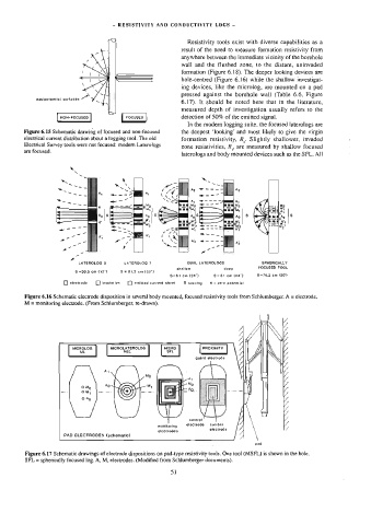
Figure 6.16 Schematic electrode disposition in several body mounted, focused resistivity tools from Schlumberger. A = electrode,
M = monitoring electrode. (From Schlumberger, re-drawn).
MICROLOG MICROLATEROLOG MICRO PROXIMITY
ML MLL SFL
guard electrode
Ay
Ma
© My Ao My
—_— OM, ~—- a
° Ao
/
monitoring elecirode electrode
coatrol
current
electrodes
PAD ELECTRODES (schematic)
pad
Figure 6.17 Schematic drawings of electrode dispositions on pad-type resistivity tools. One tool (MSFL) is shown in the hole.
SFL = spherically focused log. A, M, electrodes. (Modified from Schiumberger documents).
5]