
Page 62 - The Geological Interpretation of Well Logs
P. 62
- THE GEOLOGICAL INTERPRETATION OF WELL LOGS -
Table 6.6 Resistivity (conductivity) measuring tools (see also these tools are best used in holes drilled with conductive
Figures, 6.14, 6.17 and symbols in Table 6.4). (salt) muds, (see Section 6.6). Of the very shallow ‘look-
ing’, pad mounted devices, the Micro-spherically focused
Tool Symbol Resistivity
log of Schlumberger (MSFL) or equivalent from other
companies, is the one most frequently used for a good
Pad
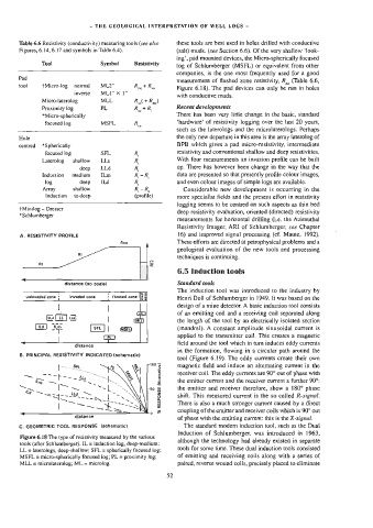
measurement of flushed zone resistivity, R,, (Table 6.6,
tool {Micro-log normal ML2” Rt Ry
Figure 6.18). The pad devices can only be run in holes
inverse MLI" X 1”
with conductive muds.
Micro-laterolog MLL RC +R
Proximity log PL Rt, Recent developments
*Micro-spherically There has been very little change in the basic, standard
focused log MSFL R, ‘hardware’ of resistivity logging over the last 20 years,
such as the laterologs and the microlaterologs. Perhaps
Hole the only new departure in this area is the array laterolog of
BPB which gives a pad micro-resistivity, intermediate
centred *Spherically
resistivity and conventional shallow and deep resistivities.
focused log SFL R,
Laterolog shallow —_ LLs R, With four measurements an invasion profile can be built
up. There has however been change in the way that the
deep LLd R
Induction medium ILm R,-R, data are presented so that presently profile colour images,
log deep ILd R, and even colour images of simple logs are available.
Array shallow R,-R, Considerable new development is occurring in the
Induction to deep (profile) more specialist fields and the present effort in resistivity
logging seems to be centred on such aspects as thin bed
tMinilog — Dresser
deep resistivity evaluation, oriented (directed) resistivity
*Schlumberger
measurements for horizontal drilling (ie. the Azimuthal
Resistivity Imager, ARI of Schlumberger, see Chapter
16) and improved signal processing (cf. Maute, 1992).
A. RESISTIVITY PROFILE
Rxo These efforts are directed at petrophysical problems and a
geological evaluation of the new tools and processing
Ri
techniques is continuing.
Rt g
6.5 Induction tools
distance (no scale) Standard toots
The induction too] was introduced to the industry by
1 , > g
uninvaded zone ' invaded zone , flushed zone lz 3
Henn Doll of Schlumberger in 1949. It was based on the
design of a mine detector. A basic induction tool consists
CML) of an emitting coil and a receiving coil separated along
Lid to} |
the length of the tool by an electrically isolated section
ua} typ [sr] | aay (mandrel). A constant amplitude sinusoidal current is
applied to the transmitter coi]. This creates a magnetic
|
field around the tool which in turn induces eddy currents
“ distance
in the formation, flowing in a circular path around the
B. PRINCIPAL RESISTIVITY INDICATED (schamatic)
too] (Figure 6.19). The eddy currents create their own
[vn SPL g magnetic field and induce an alternating current in the
_. ° s receiver coi]. The eddy currents are 90° out of phase with
iad _ ~~ s &
the emitter current and the receiver current a further 90°:
Lan ~ TO 2
“ee ~ w
the emitter and receiver therefore, show a 180° phase
ig~ ~~ ~~ un ~L 2 shift. This measured current is the so called R-signal.
|ao2S>-~=s 9
There is also a much stronger current caused by a direct
| SE
<“ & coupling of the emitter and receiver coils which is 90° out
distance
of phase with the emitting current: this is the X-signal.
Cc. GEOMETRIC TOOL RESPONSE (schematic) The standard modern induction tool, such as the Dual
Induction of Schlumberger, was introduced in 1963,
Figure 6.18 The type of resistivity measured by the various
although the technology had already existed in separate
tools (after Schlumberger). IL = induction log, deep-medium:
tools for some time. These dual induction tools consisted
LL = laterologs, deep-shallow; SFL = spherically focused log;
MSFL = micro-spherically focused log; PL = proximity log; of emitting and receiving coils along with a series of
MLL = microlaterolog; ML = microlog. paired, reverse wound coils, precisely placed to eliminate
52