
Page 97 -
P. 97
The Practical Pumping Handbook .... _ =_ .................... ::::::::::::::::::::::::::::: . .- _
H System
Curve
Design B.E.P.
Head
Design Q
Flow
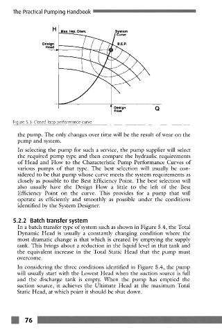
Figure 5.3 Closed loop performance curve
the pump. The only changes over time will be the result of wear on the
pump and system.
In selecting the pump for such a service, the pump supplier will select
the required pump type and then compare the hydraulic requirements
of Head and Flow to the Characteristic Pump Performance Curves of
various pumps of that type. The best selection will usually be con-
sidered to be that pump whose curve meets the system requirements as
closely as possible to the Best Efficiency Point. The best selection will
also usually have the Design Flow a little to the left of the Best
Efficiency Point on the curve. This provides for a pump that will
operate as efficiently and smoothly as possible under the conditions
identified by the System Designer.
5.2.2 Batch transfer system
In a batch transfer type of system such as shown in Figure 5.4, the Total
Dynamic Head is usually a constantly changing condition where the
most dramatic change is that which is created by emptying the supply
tank. This brings about a reduction in the liquid level in that tank and
the equivalent increase in the Total Static Head that the pump must
overcome.
In considering thc three conditions identified in Figure 5.4, the pump
will usually start with the Lowcst Head when thc suction source is full
and the discharge tank is empty. When the pump has emptied the
suction source, it achicvcs the Ultimate Hcad at the maximum Total
Static Head, at which point it should bc shut down.