
Page 98 -
P. 98
[ ......... , mr ' 'I [llrl[l[[[ "Inllll ' Pump Selection and Purchasing
Discharge Tank 'Ultimate
Head
liiiiiiiiiiiiiiiiiiiiiiiiiiiiiiiiiiiiiiiiiiiiiiiiiiiiiiiiiiiiiiiiiiiiiit
Variable
Head
Lowest
Head
I . . . . . . . . .
::::::::::::::::::::::::::::::::::::::::::::::::::::::::::::::::::::::::::::::::
::::::::::::::::::::::::::::::::::::::::::::::::::::::::::::::::::::::::::::::::
::::::::::::::::::::::::::::::::::::::::::::::::::::::::::::::::::::::::::::::::
::::::::::::::::::::::::::::::::::::::::::::::::::::::::::::::::::::::::::::::::
iiiiiiiiiiiiiiii!i!iiiiiiiii!iiiiiiiiiiii!iiiiiiiiiii!iiiiiiiiiiii!i!iiiiiiiiii.
i!iiiiiiiiii!i!i!i!iiiiiiiiiiiiiiiiiiiiii!iiiiiiiiiiiiiiiiiiii!iiiiiiiiiiiiiii?
:::::::::::::::::::::::::::::::::::::::::::::::::::::::::::::::::::::::::::::::
,................................_.................................
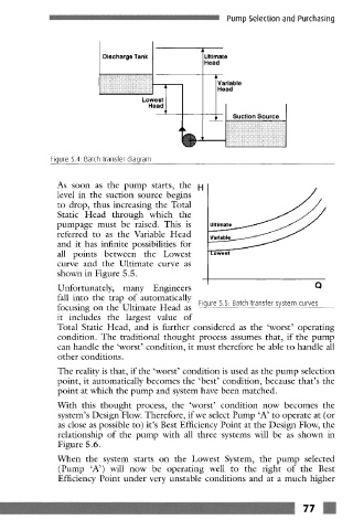
Figure 5.4: Batch transfer diagram
As soon as the pump starts, the
level in the suction source begins
to drop, thus increasing the Total
Static Head through which the
pumpagc must be raised. This is
referred to as the Variable Head
and it has infinite possibilities for
all points between the Lowest
curve and the Ultimate curve as
shown in Figure 5.5.
Q
Unfortunately, many Engineers
fall into the trap of automatically
focusing on the Ultimate Head as Figure 5.5 Batch transfer system curves
it includes the largest value of
Total Static Head, and is further considered as the 'worst' operating
condition. The traditional thought process assumes that, if the pump
can handle the 'worst' condition, it must therefore be able to handle all
other conditions.
The reality is that, if the 'worst' condition is used as the pump selection
point, it automatically becomes the 'best' condition, because that's the
point at which the pump and system have been matched.
With this thought process, the 'worst' condition now becomes the
system's Design Flow. Therefore, if we select Pump 'A' to operate at (or
as close as possible to) it's Best Efficiency Point at the Design Flow, the
relationship of the pump with all three systems will be as shown in
Figure 5.6.
When the system starts on the Lowest System, the pump selected
(Pump 'A') will now be operating well to the fight of the Best
Efficiency Point under very unstable conditions and at a much higher
m m
m _ . . . . . . . . . . . . . . . . . . . . . . . . . . . . . . . . . . . . . . . . . . . . . . . . . . . . . . . . . . . . . . . . . . . . . . . . . . . . . . . . . . . . . . . . . . . . . . . . . . _ ................