
Page 100 -
P. 100
- Pump Selection and Purchasing
/
Pump B ~ /
Worst Case Operat~~f /
c
Design C~ Design Q
Flow Flow
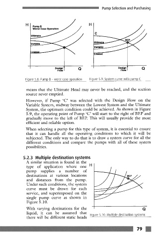
Figure 5.8. Pump B- worst case operation Figure 5.9: System curve with pump C
means that the Ultimate Head may never be reached, and the suction
source never emptied.
However, if Pump 'C' was selected with the Design Flow on the
Variable System, midway between the Lowest System and the Ultimate
System, the optimum condition could be achieved. As shown in Figure
5.9, the operating point of Pump 'C' will start to the fight of BEP and
gradually move to the left of BEE This will usually provide the most
efficient and reliable option.
When selecting a pump for this type of system, it is essential to ensure
that it can handle all the operating conditions to which it will be
subjected. The only way to do that is to draw a system curve for all the
different conditions and compare the pumps with all of these system
possibilities.
.2.3 Multiple destination systems
A similar situation is found in the
type of application where one H
pump supplies a number of
destinations at various locations
and distances from the pump.
Under such conditions, the system
curve must be drawn for each
service, and superimposed on the
single pump curve as shown in
Figure 5.10.
With varying destinations for the Q
liquid, it can be assumed that Figure 5.10 Multiple destination systems
there will be different static heads
79