
Page 78 - The Tribology Handbook
P. 78
Plain bearing form and installation A12
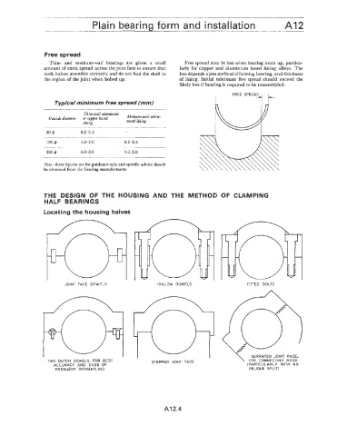
Free spread
Thin- and medium-wall bearings are given a small Free spread may be lost when bearing heats up, particu-
amount of extra spread across the joint face to ensure that larly for copper and aluminium based lining alloys. The
both halves assemble correctly and do not foul the shaft in loss depends upon method of forming bearing, and thickness
the region of the joint when bolted up. of lining. Initial minimum free spread should exceed the
likely loss if bearing is required to be reassembled.
FypicaJ minimum free spread (mm)
Thin-wall aluminium
Outside diamettr or copper based Medium-wall white-
lining metal lining
100 4 1.0-2.0 0.2-0.5
~~ ~
300 ij 4.0-8.0 1 .o-2.0
Note: these figures are for guidance only and specific advice should
be obtained from the bearing manufacturers.
THE DESIGN OF THE HOUSING AND THE METHOD OF CLAMPING
HALF BEARINGS
Locating the housing halves
JOIN'I FACE DOWELS HOLLOW DOWELS FITTED BOLTS
SERRATED JOINT FACE,
TWO DUTCH DOWELS, FOR BEST STEPPED JOINT FACE \ FOR CONNECTING RODS
ACCURACY AND EASE OF (PARTICULARLY WITH AN
FREQUENT DISMANTLING OBLIQUE SPLIT)
A12.4