
Page 79 - The Tribology Handbook
P. 79
A12 Plain bearing form and installation
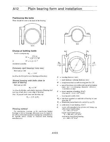
Positioning the bolts
These should be close to the back of the bearing.
I
BAD
GOOD
Choice of bolting loads
Load to compress nip
Ebtm
W=
.n (D-t) x IO6
or W = b t 4 x
whichever is smaller.
Extremely rigid housing (very rare)
Bolt load per side
wb = 1.3 w
(to allow for friction between bearing and housing)
D = housing diameter (mm)
Normal housing with bolts close to t = steel thickness+) lining thickness (mm)
back of bearing W = compression load on each bearing joint face (N)
Bolt load per side m = sum of maximum circumferential nip on both halves
Wb==2W (mm) [m = n+n(housing diametral tolerance)
+tolerance on nip]
(to allow for friction, and relative moments of bearing shell
and line of bolt about outer edge of housing). E = elastic modulus of backing (N/m2)
(For steel E = 0.21 x 10” N/m2)
Note: Ifjournal loads react into housing cap
Wb = 2 w+* wj b = bearing axial width (mm)
wb = bolt load required on each side of bearing to com-
press nip (N)
Wj = Maximum journal load to be carried by cap (N)
4 = yield stress of steel backing (N/m2)
4 varies with manufacturing process and lining, e.g.
Housing material white-metal lined bearing
For non-ferrous housings, or for non-ferrous backed 4 = 350x lo6 N/mZ
bearings in ferrous housings, allowance must be made for copper based lined bearing
the effects of thermal expansion causing loss of interference 4 = 300-400 x 1 O6 N/m2
fit. Specific advice should be obtained from bearing aluminium based lined bearing
manufacturers. 4 = 600~ lo6 N/m2
AI 2.5