
Page 73 - The Tribology Handbook
P. 73
AI 1 Crankshaft bearings
LUBRICANT FEED SYSTEM INFLUENCE OF ENGINE COMPONENT
Except for small low-cost machines, oil feed is by a DESIGN ON BEARING DESIGN
pressurised system consisting of a sump or reservoir, a AND PERFORMANCE
mechanical pump with pressure-regulating valve and Housing tolerances
by-pass, one or more filters and an arrangement of pipes
or ducts. The capacity of the system must be adequate Geometric accuracy (circularity, parallelism, ovality)
to feed all bearings and other components even after should be to H6 tolerances.
maximum permissible wear has developed. Lobing or waviness of the surface not to exceed 0.0001
A guide to the flow through a conventional central of diameter.
circumferentially grooved bearing is given by Run-out of thrust faces not to exceed 0.0003 of diameter,
total indicator reading.
kpC2 d
e= -.- (1.5 E2+1) Surface finish :
t l b Journals 0.2-0.25 pm Ra (8-10 pin cla)
where Q = flow rate, m3/sec (gal/min) Gudgeon pins 0.1-0.16 pm Ra (4-6 pin cla)
p = oil feed pressure, N/mZ (lbf/inz) Housing bores 0.75-1.6 pm Ra (3MO pin cla)
C, = diametral clearance, m (in) Alignment of adjacent housing should be within 1 in
q = dynamic viscosity, Ns/mZ (cP) 10000 to 1 in 12000.
d = bearing bore, m (in)
b = land width, m (in)
E = eccentricity ratio Bearing housing bolts
k = constant These must be stressed to take with safety the sum of
= 0.0327 for SI units the loads due to compressing the bearing in its housing,
(4.86 x lo" for Imperial units) and those due to the dynamic forces acting on the journal.
For most purposes it is sufficient to calculate the flow
for a fully eccentric shaft, Le. where E = 1.
As a guide to modern practice, in medium/large diesel Housing stiffness
engines, oil-flow requirements at 3.5 x lo5 N/mz (50 lbf/ Local deflections under load have a disastrous effect on
in2) pressure are as follows : the fatigue strength of a bearing, causing fretting on the
Bedplate gallery to mains (with piston cooling), back, increased operating temperature and lower failure
0.4 l/min/h.p. (5 gal/h/h.p.) load. Housings, particularly connecting-rod eyes, should
Mains to big end (with piston cooling), be as nearly as possible of uniform stiffness all round and
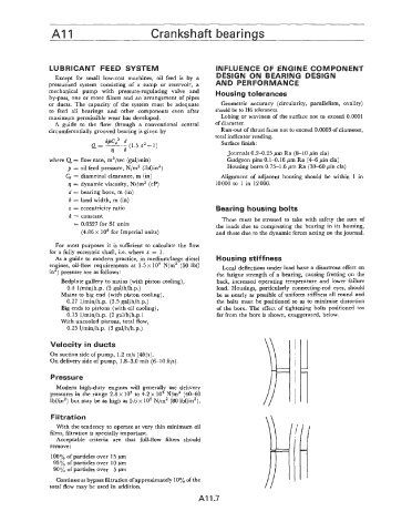
0.27 1 /min/h.p. (3.5 gal/h/h.p.) the bolts must be positioned so as to minimise distortion
Big ends to pistons (with oil cooling), of the bore. The effect of tightening bolts positioned too
0.15 l/min/h.p. (2 gal/h/h.p.) far from the bore is shown, exaggerated, below.
With uncooled pistons, total flow,
0.25 l/min/h.p. (3 gal/h/h.p.)
Velocity in ducts
On suction side of pump, 1.2 m/s (4ft/s).
On delivery side of pump, 1.8-3.0 m/s (6-10 ft/s).
Pressure
Modern high-duty engines will generally use delivery
pressures in the range 2.8 x lo5 to 4.2 x lo5 N/m2 (40-60
lbf/in2) but may be as high as 5.6~ lo5 N/m2 (80 Ibf/in2).
Filtration
With the tendency to operate at very thin minimum oil
films, filtration is specially important.
Acceptable criteria are that full-flow filters should
remove :
lOOyo of particles over 15 pm
95% of particles over 10 pm
90% of particles over 5 pm
Continuous bypass filtration of approximately 10% of the
total Aow may be used in addition.
A11.7