
Page 68 - The Tribology Handbook
P. 68
Cranks haft bearings AI 1
ELECTION OF PLAIN BEARING MATERIALS
Properties of typical steel-backed materials
Lining or overlny Guidance peak loading Recommended
Nominal Relative
Lining materials composition thickness fatigue limits Journal
O/ strength hardness
/Q mm in MN/mZ Ibf/inz V.P.N.
Tin-based white metal Sn 87 Over 0.1 Over 0.004 1 .O 12-14 1800-2000 160
Sb 9
cu 4 Up to 0.1 Up to 0.004 1.3 14-17 2OOQ-2500 160
Pb 0.35 ma<.
Tin-based white meta: Sn 89 No overlay 1.1 12-15 1800-2200 160
with cadmium Sb 7.5
cu 3
C:d 1
~~ ~~
Sintered copper-lead, Cu 70 0.05 0.002 1.8 21-23 3QO0-35QO( I) 230
overlay plated with
lead-tin Pb 30 0.025 0.001 2.4 28-3 1 400&4500(1) 280
~~ ~
Cast copper-lead, overlay Ch 76 0.025 0.001 2.4 31 4500(1) 300
plated with lead-tin Pb 24
or lead-indium
Sintered lead-bronze, cu 74 0.025 0.001 2.4 28-3 1 400@4500(1) 400
overlay plated with E’b 22
lead-tiin S8n 4
Aluminium-tin AI 60 No overlay 1.8 2 1-23 3000-3500 230
Sn 40
~___
Aluminium-tin AI 80 No overlay 3 42 6000 230
Sn 20
Aluminium-tin (1) AI 92 No overlay 3.5 48 7000 400
plated with Sn 6
lead-tin Clu 1
Ni 1
Aluminium-tin-silicon (2) AI 82 No overlay 3.7 52 7500 250
Sn 12
Si 4
cu 2
(1) Limit set by overlay fatigue in the case of medium/large diesel engines.
(2) Particularly suitable for use with nodular iron crankshafts.
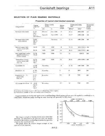
Suggested limits are for big-end applications in medium/large diesel engines and are not to be applied to crossheads or to
compressors. Maximum design loadings for main bearings will generally be 20% lower.
LINING THICKNESS, in
W
The fatigue strength of bearing metals vanes with their 2
+
thickness. As indicated in the previous table the fatigue 5
strength of the overlay on a bearing material often provides K
a limit to the maximum load. 0.4 0.10 0.15 0.20 0
w - 0.05
0.3
The graph shows the relative fatigue strength of two 5
types of overlay material. LINING THICKNESS, rnm
AI 1.2