
Page 70 - The Tribology Handbook
P. 70
Crankshaft bearings AI 1
Computation of film thickness
If the film thickness conditions are likely to be critical, computation of the theoretical film thickness is desirable and
several computer programmes are available.
Typical computer programme ussumptiom Znterpretutzon of results
Bearings are circular The results cannot be used absolutely to determine
Journals are circular whether any given hearing will or will not with-
Perfect alignment stand the conditions of operation
Uniform viscosity around the bearing However, they are useful as a means of comparison
Effect of pressure on viscosiity is ignored with similar engines, or to indicate the effect of
Surfaces are rigid design changes. They provide a guided estimate
Crankcasce and crankshaft do not distort of the probability of success
Depending on which programme is used, most bearings which are known to operate satisfactorily have computed
minimum film thicknesses that are no lower than the following:
Mains 0.0025-0.0042 mm (0.0001-0.000 17 in)
Big ends 0.002-0.004 mm (0.00008-0.000 15 in)
Means of improving oil film thickness
Modify crankshaft balance to reduce magnitude of Aim at acceptable compromise between factorsincluding :
rotating component of force. Firing loads
Modify firing order, e.g. to eliminate successive firing Inertia loads
of two or more cylinders adjacent to one bearing. Crankshaft stiffness
Increase bearing area to reduce specific loading, increase Torsional characteristics
of land width being more effective than increase of dia- Engine balance
meter. Stiffness of big-end eye
For big-end bearing, reduce reciprocative and/or rotat- Overall length of assembly
ing mass of con-rod.
Each factor must be considered both on its own merits
and in relation to others on which it has an effect.
BEARING FEATURES
General rilles for grooving in crankshaft bearings
Never use a groove unless for a valid reason, and under no circumstances use a groove reaching in an axial direction.
For many engine applications a plain, central circumferential groove is used, e.g. to permit oil to be fed to a main bearing
and thence, without interruption, to a big-end bearing via a drilled connecting rod to a small-end bearing.
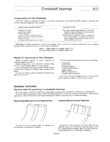
Recommended groove configurations Undesirable grooving features
The groove may be formed within the bearing wall Gutterways or oil pockets at the horns. These do not
provided the wall thickness is adequate. trap dirt and are not needed for axial distribution of oil
in a typical modern bearing. They can cause local over-
loading along line A-A, and fatigue breakdown.
AI 1.4