
Page 129 - The Mechatronics Handbook
P. 129
concept of causality, which captures the input–output relationship between power-conveying variables
in a system. The bond graph approach provides a way to understand and mathematically model basic as
well as complex mechanical systems that is consistent with other energetic domains (electric, electrome-
chanical, thermal, fluid, chemical, etc.).
Physical Variables and Power Bonds
Power and Energy Basis
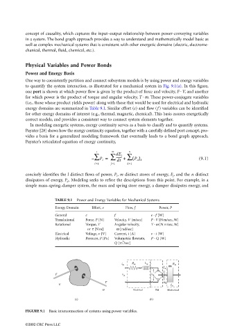
One way to consistently partition and connect subsystem models is by using power and energy variables
to quantify the system interaction, as illustrated for a mechanical system in Fig. 9.1(a). In this figure,
one port is shown at which power flow is given by the product of force and velocity, F · V, and another
for which power is the product of torque and angular velocity, T · ω. These power-conjugate variables
(i.e., those whose product yields power) along with those that would be used for electrical and hydraulic
energy domains are summarized in Table 9.1. Similar effort (e) and flow (f ) variables can be identified
for other energy domains of interest (e.g., thermal, magnetic, chemical). This basis assures energetically
correct models, and provides a consistent way to connect system elements together.
In modeling energetic systems, energy continuity serves as a basis to classify and to quantify systems.
Paynter [28] shows how the energy continuity equation, together with a carefully defined port concept, pro-
vides a basis for a generalized modeling framework that eventually leads to a bond graph approach.
Paynter’s reticulated equation of energy continuity,
l m n
∑ ∑ dE j ( ∑
– P i = ------- + P d ) k (9.1)
dt
i=1 j=1 k=1
concisely identifies the l distinct flows of power, P i , m distinct stores of energy, E j , and the n distinct
dissipators of energy, P d . Modeling seeks to refine the descriptions from this point. For example, in a
simple mass–spring–damper system, the mass and spring store energy, a damper dissipates energy, and
TABLE 9.1 Power and Energy Variables for Mechanical Systems
Energy Domain Effort, e Flow, f Power, P
General e f e · f [W]
Translational Force, F [N] Velocity, V [m/sec] F · V [N m/sec, W]
Rotational Torque, T Angular velocity, T · ω [Nm/sec, W]
or τ [N m] ω [rad/sec]
Electrical Voltage, v [V] Current, i [A] v · i [W]
Hydraulic Pressure, P [Pa] Volumetric flowrate, P · Q [W]
3
Q [m /sec]
R m L m
i in B m
T m
F v in v m
T w m
V J m
w Electrical EM Mechanical
(a) (b)
FIGURE 9.1 Basic interconnection of systems using power variables.
©2002 CRC Press LLC