
Page 130 - The Mechatronics Handbook
P. 130
the interconnection of these elements would describe how power flows between them. Some of the details
for accomplishing these modeling steps are presented in later sections.
One way to proceed is to define and categorize types of system elements based on the reticulated
energy continuity Eq. (9.1). For example, consider a system made up only of rigid bodies as energy stores
(in particular of kinetic energy) for which P d = 0 (we can add these later), and in general there can be l
ports that could bring energy into this purely (kinetic)energy-storing system which has m distinct ways
to put energy into the rigid bodies. This is a very general concept, consistent with many other ways to
model physical systems. Howevever, it is this foundation that provides for a generalized way to model
and integrate different types of energetic systems.
The schematic of a permanent-magnet dc (PMDC) motor shown in Fig. 9.1(b) illustrates how power
variables would be used to identify inteconnection points. This example also serves to identify the need
for modeling mechanisms, such as the electromechanical (EM) interaction, that can represent the
exchange of energy between two parts of a system. This model represents a simplified relationship between
electrical power flow, v · i, and mechanical power flow, T · ω, which forms the basis for a motor model.
Further, this is an ideal power-conserving relationship that would only contain the power flows in the
energy continuity equation; there are no stores or dissipators. Additional physical effects would be
included later.
Power and Signal Flow
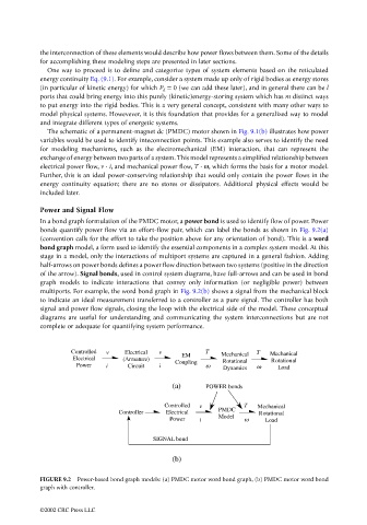
In a bond graph formulation of the PMDC motor, a power bond is used to identify flow of power. Power
bonds quantify power flow via an effort-flow pair, which can label the bonds as shown in Fig. 9.2(a)
(convention calls for the effort to take the position above for any orientation of bond). This is a word
bond graph model, a form used to identify the essential components in a complex system model. At this
stage in a model, only the interactions of multiport systems are captured in a general fashion. Adding
half-arrows on power bonds defines a power flow direction between two systems (positive in the direction
of the arrow). Signal bonds, used in control system diagrams, have full-arrows and can be used in bond
graph models to indicate interactions that convey only information (or negligible power) between
multiports. For example, the word bond graph in Fig. 9.2(b) shows a signal from the mechanical block
to indicate an ideal measurement transferred to a controller as a pure signal. The controller has both
signal and power flow signals, closing the loop with the electrical side of the model. These conceptual
diagrams are useful for understanding and communicating the system interconnections but are not
complete or adequate for quantifying system performance.
Controlled v Electrical v T Mechanical T Mechanical
Electrical (Armature) EM Rotational Rotational
Power i Circuit i Coupling w Dynamics w Load
(a) POWER bonds
Controlled v T Mechanical
Controller Electrical PMDC Rotational
Power i Model w Load
SIGNAL bond
(b)
FIGURE 9.2 Power-based bond graph models: (a) PMDC motor word bond graph, (b) PMDC motor word bond
graph with controller.
©2002 CRC Press LLC