
Page 528 - The Mechatronics Handbook
P. 528
0066_frame_C19 Page 150 Wednesday, January 9, 2002 5:32 PM
FIGURE 19.125 Schematic diagram illustrating the operation principle of a momentum-transfer based flow sensor.
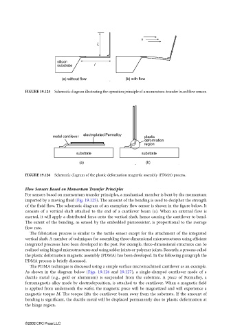
FIGURE 19.126 Schematic diagram of the plastic deformation magnetic assembly (PDMA) process.
Flow Sensors Based on Momentum Transfer Principles
For sensors based on momentum transfer principles, a mechanical member is bent by the momentum
imparted by a moving fluid (Fig. 19.125). The amount of the bending is used to decipher the strength
of the fluid flow. The schematic diagram of an exemplary flow sensor is shown in the figure below. It
consists of a vertical shaft attached to the end of a cantilever beam (a). When an external flow is
exerted, it will apply a distributed force onto the vertical shaft, hence causing the cantilever to bend.
The extent of the bending, as sensed by the embedded piezoresistor, is proportional to the average
flow rate.
The fabrication process is similar to the tactile sensor except for the attachment of the integrated
vertical shaft. A number of techniques for assembling three-dimensional microstructures using efficient
integrated processes have been developed in the past. For example, three-dimensional structures can be
realized using hinged microstructures and using solder joints or polymer joints. Recently, a process called
the plastic deformation magnetic assembly (PDMA) has been developed. In the following paragraph the
PDMA process is briefly discussed.
The PDMA technique is discussed using a simple surface micromachined cantilever as an example.
As shown in the diagram below (Figs. 19.126 and 19.127), a single-clamped cantilever made of a
ductile metal (e.g., gold or aluminum) is suspended from the substrate. A piece of Permalloy, a
ferromagnetic alloy made by electrodeposition, is attached to the cantilever. When a magnetic field
is applied from underneath the wafer, the magnetic piece will be magnetized and will experience a
magnetic torque M. The torque lifts the cantilever beam away from the substrate. If the amount of
bending is significant, the ductile metal will be displaced permanently due to plastic deformation at
the hinge region.
©2002 CRC Press LLC