
Page 734 - The Mechatronics Handbook
P. 734
0066_Frame_C23 Page 42 Wednesday, January 9, 2002 1:56 PM
Free Body Diagram
F F
Damper Spring D s
Mass m
z (+) z (+)
Piezoelectric F
Force, F P
P
(a) (b)
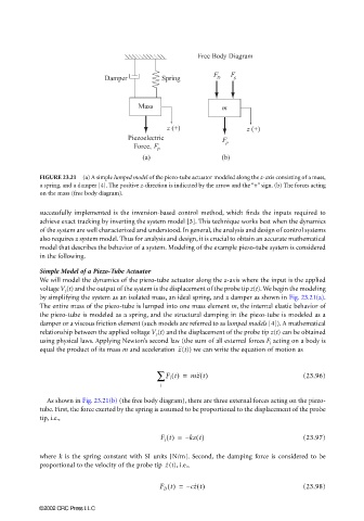
FIGURE 23.21 (a) A simple lumped model of the piezo-tube actuator modeled along the z-axis consisting of a mass,
a spring, and a damper [4]. The positive z-direction is indicated by the arrow and the “+” sign. (b) The forces acting
on the mass (free body diagram).
successfully implemented is the inversion-based control method, which finds the inputs required to
achieve exact tracking by inverting the system model [3]. This technique works best when the dynamics
of the system are well characterized and understood. In general, the analysis and design of control systems
also requires a system model. Thus for analysis and design, it is crucial to obtain an accurate mathematical
model that describes the behavior of a system. Modeling of the example piezo-tube system is considered
in the following.
Simple Model of a Piezo-Tube Actuator
We will model the dynamics of the piezo-tube actuator along the z-axis where the input is the applied
voltage V z (t) and the output of the system is the displacement of the probe tip z(t). We begin the modeling
by simplifying the system as an isolated mass, an ideal spring, and a damper as shown in Fig. 23.21(a).
The entire mass of the piezo-tube is lumped into one mass element m, the internal elastic behavior of
the piezo-tube is modeled as a spring, and the structural damping in the piezo-tube is modeled as a
damper or a viscous friction element (such models are referred to as lumped models [4]). A mathematical
relationship between the applied voltage V z (t) and the displacement of the probe tip z(t) can be obtained
using physical laws. Applying Newton’s second law (the sum of all external forces F i acting on a body is
equal the product of its mass m and acceleration (t)) we can write the equation of motion asz ˙˙
∑ F i t() = mz ˙˙ t() (23.96)
i
As shown in Fig. 23.21(b) (the free body diagram), there are three external forces acting on the piezo-
tube. First, the force exerted by the spring is assumed to be proportional to the displacement of the probe
tip, i.e.,
F s t() = – kz t() (23.97)
where k is the spring constant with SI units [N/m]. Second, the damping force is considered to be
z ˙
proportional to the velocity of the probe tip (t), i.e.,
F D t() = – cz ˙ t() (23.98)
©2002 CRC Press LLC