
Page 733 - The Mechatronics Handbook
P. 733
0066_Frame_C23 Page 41 Wednesday, January 9, 2002 1:56 PM
nonlinear, time-varying, and multivariable systems, whereas the transfer-function approach is suited to
linear time-invariant (LTI) systems [1, Chapter 3]. In addition, models expressed in first order state-
space form in the time-domain can be readily solved by a digital computer or microprocessor, which
makes this approach quite useful for the design and control of modern mechatronic systems. Further-
more, there is a wide variety of available computer software, such as MATLAB [2], that take advantage
of the state-space form for analyzing and solving design problems. Therefore, the state-space approach
can be used to investigate the behavior and facilitate in the design of both continuous- and discrete-time
systems, the fundamentals of which will be the focus of this section.
In the following, we begin with an example: the modeling of a piezoceramic actuator and use the
example throughout the section. The concept of a system state is introduced and we explain the state-
space equation for linear systems and present its solution. The topic of linearization of nonlinear systems
is briefly mentioned. The relationships between time- and frequency-domain models are discussed and
a procedure for obtaining a state-space model using experimental frequency-domain (frequency-
response) data is presented. This section closes with a discussion of discrete-time state-space modeling
and concluding remarks. Useful MATLAB commands are also included as footnotes.
States and the State-Space
An Example Piezoceramic Actuator
We begin by modeling a piezoceramic actuator, which is an example mechatronic (electromechanical)
system. When a voltage is applied to a piezoceramic material, its dimension changes. This change in
dimension can be used to precisely position an object or tool (such as a sensor), therefore making
piezoceramics suitable actuators for a wide variety of applications. For example, due to their ability to
achieve positioning with sub-nanometer level precision, piezoceramic actuators have become ideal for
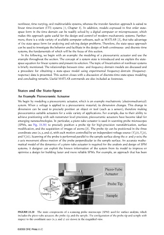
emerging nanotechnologies. In particular, a piezo-tube actuator is used in scanning probe microscopes
(SPMs, see Fig. 23.20) to precisely position a probe tip for high-precision nanofabrication, surface
modification, and the acquisition of images of atoms [3]. The probe tip can be positioned in the three
coordinate axes (x, y, and z), with each motion controlled by an independent voltage source (V x (t), V y (t),
and V z (t)). Scanning of the probe is performed parallel to the sample surface along the x- and y-axis; the
z-axis movement allows motion of the probe perpendicular to the sample surface. An accurate mathe-
matical model of the dynamics of a piezo-tube actuator is required for the analysis and design of SPM
systems. A designer can exploit the known information of the system from its model to improve or
optimize a design for building faster and more reliable SPMs. For example, an approach that has been
Piezo-Tube
Actuator
Probe
Tip Probe Tip
x
Sample y
z Sample
FIGURE 23.20 The main components of a scanning probe microscope (SPM) used for surface analysis, which
includes the piezo-tube actuator, the probe tip, and the sample. The configuration of the probe tip and sample with
respect to the coordinate axes (x, y, and z) are shown in the magnified view.
©2002 CRC Press LLC