Page 740 - The Mechatronics Handbook
P. 740
0066_Frame_C23  Page 48  Friday, January 18, 2002  5:34 PM


                       with the same frequency ω and a phase shift φ [6, Chapter 8]. The output amplitude is the input amplitude
                       scaled by  M, the magnitude gain. The magnitude gain  M is found by taking the magnitude of  G(s)
                       evaluated at s = jω, i.e.,

                                                        M =  G s() s=jω                        (23.129)

                       Usually, the magnitude gain M is expressed in units of decibels (dB), i.e., M [dB] = 20log M. The phase
                       shift φ is the angle of G(s) evaluated at s = jω, i.e.,

                                                        φ =  ∠ Gs()  s=jω                      (23.130)

                       with units of degrees. The plot of the magnitude gain M and the phase shift φ versus the frequency ω
                                                                                       9
                       gives a graphical representation of the frequency-response (Bode plots) of a system.  These plots can be
                       obtained experimentally by measuring the magnitude gain and phase shift between the input and output
                       response of a system over a range of frequencies. Additionally, a system’s transfer-function can be obtained
                       from an experimental frequency-response data by using curve-fitting software. In section “Experimental
                       Modeling Using Frequency Response,” we present this approach to determine a model for a system using
                       experimental frequency-response data.

                       Transfer-Function to State-Space
                       In section “State-Space to Transfer-Function,” a transfer-function model was obtained for a system in
                       state-space form. In the following, an approach for realizing a state-space model from a transfer-function
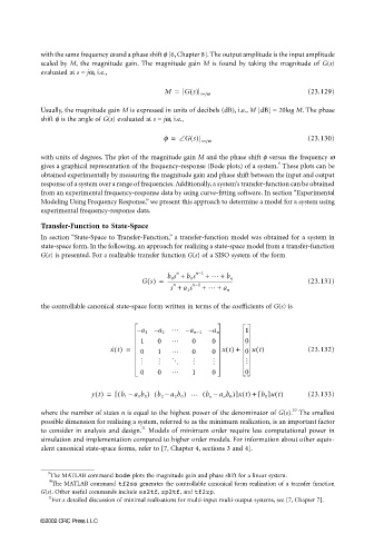
                       G(s) is presented. For a realizable transfer function G(s) of a SISO system of the form

                                                         b 0 s +  b 1 s  n−1  +  … +
                                                           n
                                                  Gs() =  ----------------------------------------------------  (23.131)
                                                                         b n
                                                          s +  a 1 s n−1 + …  +  a n
                                                          n
                       the controllable canonical state-space form written in terms of the coefficients of G(s) is

                                                          …
                                                 – a 1 – a 2  – a n−1 –  a n  1
                                                          …
                                                 1    0        0     0        0
                                         x ˙ t() =  0  1  …    0     0  xt() +  0  ut()        (23.132)
                                                  M   M   O     M    M        M
                                                          …
                                                 0    0        1     0        0

                                    yt() =  ( [  b 1 –  a 1 b 0 ) ( b 2 – a 2 b 0 ) … ( b n –  a n b 0 )]xt() + []ut()  (23.133)
                                                                                  b 0
                                                                                          10
                       where the number of states n is equal to the highest power of the denominator of G(s).  The smallest
                       possible dimension for realizing a system, referred to as the minimum realization, is an important factor
                                                  11
                       to consider in analysis and design.  Models of minimum order require less computational power in
                       simulation and implementation compared to higher order models. For information about other equiv-
                       alent canonical state-space forms, refer to [7, Chapter 4, sections 3 and 4].


                         9
                         The MATLAB command bode plots the magnitude gain and phase shift for a linear system.
                         10
                          The MATLAB command tf2ss generates the controllable canonical form realization of a transfer function
                       G(s). Other useful commands include ss2tf, zp2tf, and tf2zp.
                         11
                          For a detailed discussion of minimal realizations for multi-input multi-output systems, see [7, Chapter 7].
                      ©2002 CRC Press LLC

