Page 447 - Thomson, William Tyrrell-Theory of Vibration with Applications-Taylor _ Francis (2010)
P. 447

434                                       Random Vibrations   Chap. 13


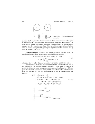
                                                                     Figure 13.5-7.  Time delay for auto-
                                                                     correlation.
                              shows  a  block  diagram  for  the  determination  of  the  autocorrelation.  The  signal
                              x(t) is delayed by  r  and multiplied,  after which  it  is integrated and  averaged. The
                              delay  time  r  is  fixed  during  each  run  and  is  changed  in  steps  or  is  continuously
                              changed by a slow sweeping technique.  If the record  is on magnetic tape,  the  time
                              delay  r  can  be  accomplished  by  passing  the  tape  between  two  identical  pickup
                              units,  as shown  in  Fig.  13.5-7.
                                  Cross  correlation.  Consider  two  random  quantities  x{t)  and  y{t).  The
                              correlation between  these  two quantities is defined  by the  equation
                                            RxyiT)  =  E[x{t)y{t  +  t )]  =( x (t )y ( t  +  t ))
                                                                                         (13.5-3)
                                                  =  lim  rj. f  x{t)y{t  +  t ) dt
                                                     T-*oo  i
                                                             /
                                                           - T 2
                              which can also be called the  cross  correlation  between the  quantities  x  and  y.
                                  Such  quantities often  arise  in  dynamical  problems.  For  example,  let  x{t) be
                              the  deflection  at  the  end  of  a  beam  due  to  a  load  F^{t)  at  some  specified  point.
                              yU)  is  the  deflection  at  the  same  point,  due  to  a  second  load  F2U)  at  a  different
                              point than the first, as illustrated in Fig.  13.5-8. The deflection due to both loads is
                              then  z{t)  = (t)  + y(C,  and  the  autocorrelation  of  z{t)  as  a  result  of  the  two
                                        x
                              loads is
                                                           + t ))
                                                 = ( [ x ( / )   -I-y(i)][j^(i +  t )  + y { t  +  t )])
                                                 = x { t ) x { t   -f-  t)>  + { x { t ) y { t    t))   (13.5-4)
                                                  {
                                                   + { y { t ) x { t  +  t))  + { y { t ) y { t  +  t)>
                                                 =       +^xy('^)  +^yy('^)  +^y(' ^)


                                                                     Figure  13.5-8.
   442   443   444   445   446   447   448   449   450   451   452