Page 142 - Troubleshooting Analog Circuits
P. 142

ADCs Can Be Tough and Temperamental                               I29


                         manufacturers don’t make much noise about noise. Ron Knapp of Maxim wrote a
                         nice explanation of this ADC noise measurement technique in EDN recently (Ref. 3).
                         I recommend his article on this subject.
                           Most ADC data sheets spell out that the only correct way to test or use an ADC is
                         with the analog signal’s ground, the digital supply’s ground, and the analog supply’s
                         ground tied together right at the ground pin of the ADC. If you don’t or can’t inter-
                         connect the grounds at the specified point, all bets are off.


                          n

          CONVERT                          0 MSB OUT
          CONVERT
          COMMAND * 0
          COMMAND
                             ADC           0
                          I   UNDER        0                       LATCHES -
                             TEST                                 (OPTIONAL) -
                                          LSB+l                              lk
                                           ”                       -. . -,
                                           A
                                                                    ,
                                                                             2k
                                         LSB  OUT                 (OPTIONAL)   2k   :;
                                         LSB OUT
                                                                         A
                       -                                                          100
                       ANALOG
                       ANALOG
                       GROUND
                       GROUND
                 LOW-NOISE
            REFERENCE-VOLTAGE SOURCE


                                                                 I     0               0
                             20
                      e-1                                             VERTICAL   HORIZONTAL
            TRIANGULAR WAVE                                            INPUT       INPUT
             GENERATOR
            (1 TO 100 HZ AS                                           -0
             APPROPRIATE)


           (b)                         (C)                         (d)
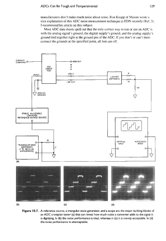
              Figure 10.7.  A reference source, a triangular-wave generator, and a scope are the major building blocks of
                         an ADC crossplot tester (a) that can reveal how much noise a converter adds to the signal it
                         is digitizing. In (b) the noise performance is ideal, whereas in (c) it is merely acceptable. In (d)
                         the noise performance is unacceptable.
   137   138   139   140   141   142   143   144   145   146   147