
Page 42 - Using ANSYS for Finite Element Analysis Dynamic, Probabilistic, Design and Heat Transfer Analysis
P. 42
composite materials • 29
• SOLID65, the 3-D reinforced concrete solid element, models
an isotropic medium with optional reinforcing in three different
user-defined orientations.
• BEAM188 and BEAM189, the 3-D finite strain beam elements,
can have their sections built up with multiple materials.
2.2.2 DeFining The LAyeReD ConFigURATion
The most important characteristic of a composite material is its layered
configuration. Each layer may be made of a different orthotropic material
and may have its principal directions oriented differently. For laminated
composites, the fiber directions determine layer orientation. Two methods
are available to define the layered configuration:
• By specifying individual layer properties.
• By defining constitutive matrices that relate generalized forces and
moments to generalized strains and curvatures (available only for
SOLID46 and SHELL99).
2.2.2.1 Specifying individual Layer Properties
With this method, the layer configuration is defined layer-by-layer from
bottom to top. The bottom layer is designated as layer 1, and additional
layers are stacked from bottom to top in the positive Z (normal) direction
of the element coordinate system. You need to define only half of the lay-
ers if stacking symmetry exists.
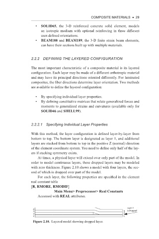
At times, a physical layer will extend over only part of the model. In
order to model continuous layers, these dropped layers may be modeled
with zero thickness. Figure 2.10 shows a model with four layers, the sec-
ond of which is dropped over part of the model.
For each layer, the following properties are specified in the element
real constant table
[R, RMORE, RMODIF]
Main Menu> Preprocessor> Real Constants
Accessed with REAL attributes.
Layer 2
4
3 4 is dropped
2 3
1 1
Figure 2.10. Layered model showing dropped layer.