
Page 46 - Using ANSYS for Finite Element Analysis Dynamic, Probabilistic, Design and Heat Transfer Analysis
P. 46
composite materials • 33
Ply 3
Ply 2
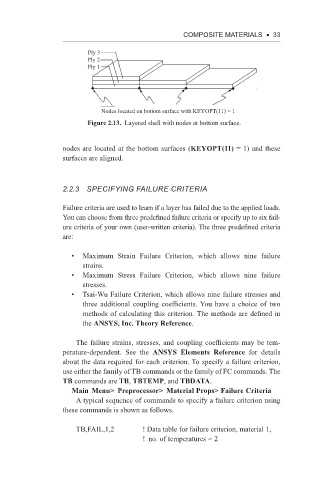
Ply 1
Nodes located on bottom surface with KEYOPT(11) = 1
Figure 2.13. Layered shell with nodes at bottom surface.
nodes are located at the bottom surfaces (KEYOPT(11) = 1) and these
surfaces are aligned.
2.2.3 SPeCiFying FAiLURe CRiTeRiA
Failure criteria are used to learn if a layer has failed due to the applied loads.
You can choose from three predefined failure criteria or specify up to six fail-
ure criteria of your own (user-written criteria). The three predefined criteria
are:
• Maximum Strain Failure Criterion, which allows nine failure
strains.
• Maximum Stress Failure Criterion, which allows nine failure
stresses.
• Tsai-Wu Failure Criterion, which allows nine failure stresses and
three additional coupling coefficients. You have a choice of two
methods of calculating this criterion. The methods are defined in
the ANSYS, Inc. Theory Reference.
The failure strains, stresses, and coupling coefficients may be tem-
perature-dependent. See the ANSYS Elements Reference for details
about the data required for each criterion. To specify a failure criterion,
use either the family of TB commands or the family of FC commands. The
TB commands are TB, TBTEMP, and TBDATA.
Main Menu> Preprocessor> Material Props> Failure Criteria
A typical sequence of commands to specify a failure criterion using
these commands is shown as follows.
TB,FAIL,1,2 ! Data table for failure criterion, material 1,
! no. of temperatures = 2