
Page 45 - Using ANSYS for Finite Element Analysis Dynamic, Probabilistic, Design and Heat Transfer Analysis
P. 45
32 • using ansys for finite eLement anaLysis
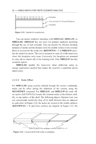
Faceplate
Core (at least 1/2 of local thickness)
Faceplate
Figure 2.11. Sandwich construction.
You can model sandwich structures with SHELL63, SHELL91, or
SHELL181. SHELL63 has one layer but permits sandwich modeling
through the use of real constants. You can modify the effective bending
moment of inertia and the distance from the middle surface to the extreme
fibers to account for the weak core. KEYOPT(9) = 1 of SHELL91 speci-
fies the sandwich option. The core is assumed to carry all of the transverse
shear; the faceplates carry none. Conversely, the faceplates are assumed
to carry all (or almost all) of the bending load. Only SHELL91 has this
sandwich option.
SHELL181 models the transverse shear deflection using as
energy equivalence method that makes the need for a sandwich option
unnecessary.
2.2.2.4 node offset
For SHELL181 using sections defined through the section commands,
nodes can be offset during the definition of the section, using the
SECOFFSET command. For SHELL91, and SHELL99 the node off-
set option (KEYOPT(11)) locates the element nodes at the bottom, mid-
dle, or top surface of the shell. The following figures illustrate how you
can conveniently model ply drop off in shell elements that are adjacent
to each other. In Figure 2.12, the nodes are located at the middle surfaces
(KEYOPT(11) = 0) and these surfaces are aligned. In Figure 2.13, the
Nodes located at the midplane with KEYOPT(11) = 0
Figure 2.12. Layered shell with nodes at midplane.